MIL-PRF-19500/246K
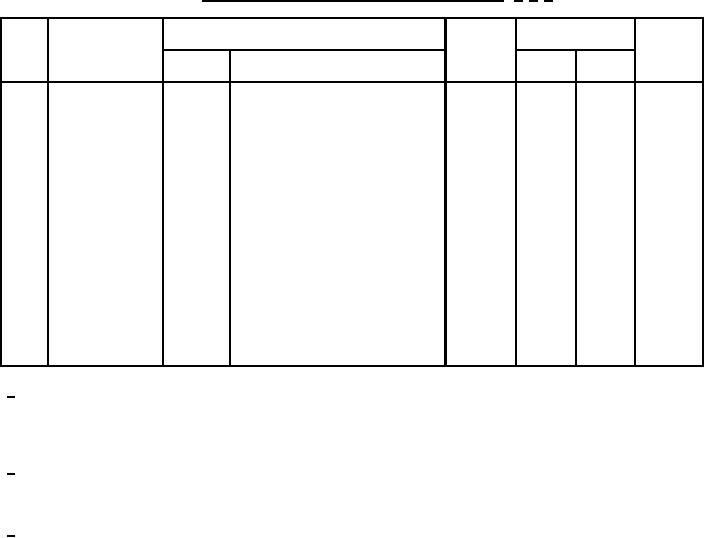
TABLE III. Groups A, B, C, D, and E electrical measurements. 1/ 2/ 3/
Step
Inspection
Symbol
Limits
Unit
Method
Conditions
Min
Max
1.
Forward voltage
4011
Pulse method:
1.55
V (pk)
VFM
IFM = 310 A (pk)
pulse width = 8.3 ms maximum;
duty cycle = 2 percent maximum
2.
Reverse current
4016
AC method:
IRM1
1N3289, R
VRM = 200 V (pk)
10
mA (pk)
VRM = 400 V (pk)
1N3291, R
10
mA (pk)
VRM = 600 V (pk)
1N3293, R
10
mA (pk)
VRM = 800 V (pk)
1N3294, R
10
mA (pk)
VRM = 1,000 V (pk)
1N3295, R
10
mA (pk)
ĆVFM
3.
Forward voltage
4011
IFM = 310 A (pk)
+0.1
V (pk)
(change)
1/ The electrical measurements for appendix E, table E-VIB (JAN, JANTX, and JANTXV) of MIL-PRF-19500 are
as follows:
a. Subgroup 2, see table III herein, steps 1 and 2.
b. Subgroup 3, see table III herein, steps 1 and 2.
c. Subgroup 6, see table III herein, steps 1 and 2.
2/ The electrical measurements for appendix E, table E-VII (all quality levels) of MIL-PRF-19500 are as follows:
a. Subgroup 2, see table III herein, steps 1 and 2.
b. Subgroup 5, see table III herein, step 2 during test.
c. Subgroup 6, see table III herein, steps 1 and 2.
3/ The electrical measurements for appendix E, table E-IX of MIL-PRF-19500 are as follows:
a. Subgroup 1, see table III herein, steps 1, 2, and 3.
b. Subgroup 2, see table III herein, steps 1, 2, and 3.
10
For Parts Inquires call Parts Hangar, Inc (727) 493-0744
© Copyright 2015 Integrated Publishing, Inc.
A Service Disabled Veteran Owned Small Business