MIL-PRF-19500/102B
Dimensions
Symbol
Notes
Inches
Millimeters
Min
Max
Min
Max
A
1.24
1.28
31.5
32.51
B
1.130
28.7
C
.50
.56
12.70
14.22
D
.55
.58
13.97
14.73
E
.045
.055
1.14
1.40
4
F
.73
.80
18.54
20.32
G
.07
.14
1.78
3.56
H
.13
.19
3.30
4.83
J
.014
.024
0.36
0.61
K
.14
.17
3.56
4.32
L
.10
.14
2.54
3.56
M
.48
.52
12.19
13.21
N
.35
.40
8.89
10.16
P
.09
.11
2.29
2.79
4
R
.050
.060
1.27
1.52
S
.81
.85
20.57
21.59
T
3
U
.14
.17
3.56
4.32
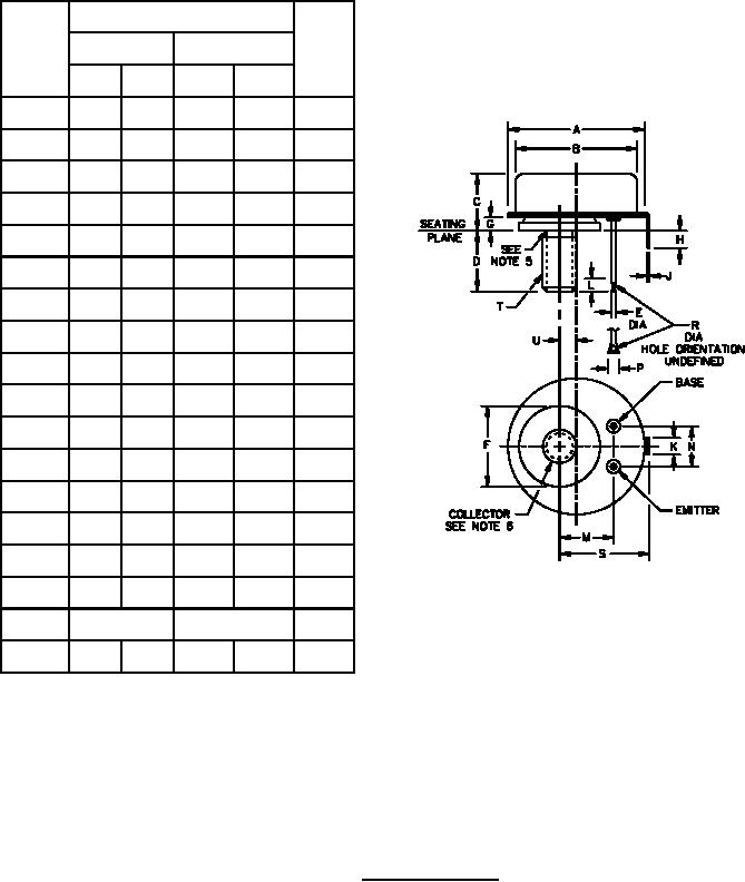
NOTES:
1. Dimension are in inches.
2. Millimeters are given for general information only.
3. See NBS Handbook H28. 5/16 24 UNF-2A
4. Two leads.
5. Reference point for temperature measurement.
6. The collector shall be internally connected to the mounting base.
FIGURE 1. Physical dimensions.
2
For Parts Inquires call Parts Hangar, Inc (727) 493-0744
© Copyright 2015 Integrated Publishing, Inc.
A Service Disabled Veteran Owned Small Business