MIL-PRF-19500/198E
TO-5
Dimensions
Symbol
Note
Inches
Millimeters
Min
Max
Min
Max
CD
.305
.335
7.75
8.51
CH
.200
.260
5.08
6.60
HD
.335
.370
8.51
9.40
LC
.200 TP
5.08 TP
LD
.016
.019
0.41
0.48
3, 7
* LL
1.500 1.750 38.1
44.45
3
LU
.016
.019
0.41
0.48
7
L1
.050
1.27
7
L2
.250
6.35
7
P
.100
2.54
6
Q
.030
0.76
8, 10
TL
.029
.045
0.74
1.14
11
TW
.028
.034
0.71
0.86
11
r
.010
0.25
11, 12
α
45° TP
45° TP
NOTES:
1. Dimension are in inches.
2. Millimeters are given for general information only.
3. All terminals are electrically insulated from the case.
4. Leads may be soldered to within .063 inch (1.60 mm) of base. Heat sinking not required if temperature-time
exposure is less than 230°C for 10 seconds.
5. This device is for socketed single-sided circuit-board, wire-in, and similar applications. Where used in double
sided or eyeletted circuit-board, or similar applications where solder bridging may occur, a dielectric washer or
other standoff device may be necessary.
6. This zone is controlled for automatic handling. The variation in actual diameter within this zone shall not exceed
.010 inch (0.25 mm).
7. The specified lead diameter applies in the zone between .050 (1.27 mm) and .250 inch (6.35 mm) from the
base seat. Between .250 inch (6.35 mm) and 1.5 (38.1 mm) a maximum of .021 inch (0.533 mm) diameter is
held. Outside of these zones the lead diameter is not controlled.
8. Body contour optional within zone defined by Q.
9. Lead 1 = cathode, lead 2 = gate, lead 3 = anode.
10. Details of outline in this zone are optional.
11. Tab is optional.
12. Dimension r (radius) applies to both inside corners of tab.
13. In accordance with ASME Y14.5M, diameters are equivalent to Φx symbology.
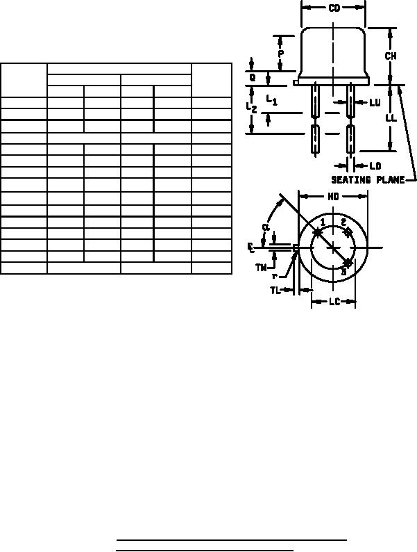
* FIGURE 1. Physical dimensions of semiconductor types 2N1870A,
2N1871A, 2N1872A and 2N1874A (TO-5).
3
For Parts Inquires call Parts Hangar, Inc (727) 493-0744
© Copyright 2015 Integrated Publishing, Inc.
A Service Disabled Veteran Owned Small Business