MIL-PRF-19500/168K
Dimensions
Ltr
Inches
Millimeters
Notes
Min
Max
Min
Max
B
.080
.136
2.03
3.45
3
CH
.300
.400
7.62
10.2
DT
.040
.075
1.02
1.9
e
.013
0.33
8
e1
.060
1.52
6
HF
.424
.437
10.8
11.1
HT
.060
.175
1.52
4.45
4
OAH
.700
.855
17.8
21.72
2
ΦD
.400
10.2
9
ΦD1
.424
10.8
2
SD
.1658 .1697
4.21
4.310
7
SL
.400
.453
10.2
11.51
SU
.078
1.98
UD
.163
.189
4.14
4.80
NOTES:
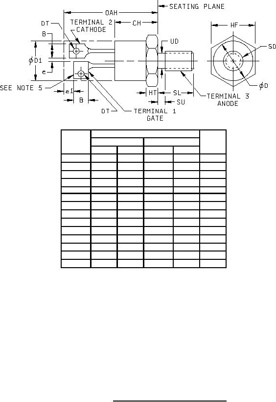
1. Dimensions are in inches. Millimeters are given for general information only.
2. Device contour, except on hex head and noted terminal dimensions, is optional within zone defined by ΦD1 and
OAH, ΦD1 not to exceed actual HF.
3. Contour and angular orientation of terminals 1 and 2, with respect to hex portion and to each other, are optional.
4. Chamfer, or undercut, on one or both ends of the hexagonal portion are optional.
5. Square or radius on end of terminal is optional.
6. Minimum difference in terminal lengths to establish datum line for numbering terminals.
7. Pitch diameter - thread 10-32 NF-2A (coated). See FED-STD-H28, "Screw-Thread Standards for Federal
Services".
8. Minimum spacing between terminals.
9. Minimum diameter of seating plane.
10. In accordance with ASME Y14.5M, diameters are equivalent to Φx symbology.
FIGURE 1. Physical dimensions (similar to TO-64).
3
For Parts Inquires call Parts Hangar, Inc (727) 493-0744
© Copyright 2015 Integrated Publishing, Inc.
A Service Disabled Veteran Owned Small Business