MIL-PRF-19500/302C
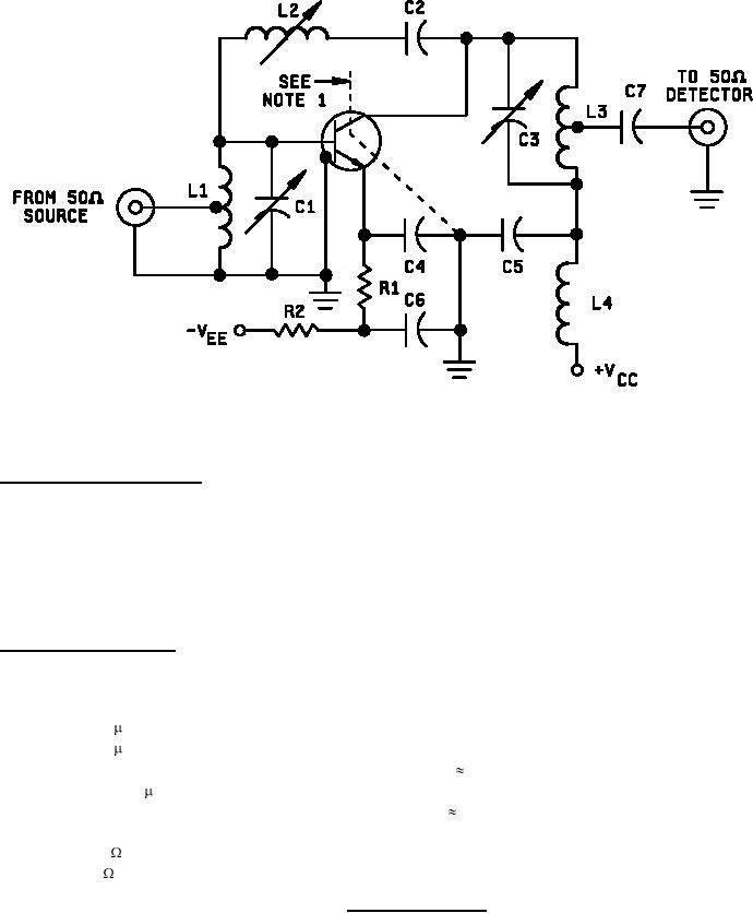
NOTE 1: External interlead shield to isolate the collector from the emitter and base leads.
NEUTRALIZATION PROCEDURE:
1. Connect a 200 MHz signal generator (with a 50 ohm output impedance) to the input terminals of the amplifier, and connect a 50
ohm rf voltmeter to the output terminals of the amplifier.
2. Apply VEE and VCC to obtain the specified conditions.
3. Adjust the output of the signal generator to approximately 10 millivolts and tune C1 and C3 for maximum output.
4. Interchange the connections to the signal generator and rf voltmeter and with sufficient signal applied at the output terminals,
tune L2 for a minimum indication on the rf voltmeter.
5. Repeat this sequence until optimum settings are obtained for all variables.
Circuit-component information:
C1
3 - 12 pF.
C2 and C7
1000 pF.
C3
1.5 - 7.5 pF.
C4 and C5
0.01 F.
C6
0.05 F.
L1
3.5 T No. 16 AWG 0.312 inch ID, 0.438 inch length, Turns ratio
2 to 1.
L2
0.4 - 0.65 H, Miller No. 4303 or equal.
L3
8 T No. 16 AWG, 0.125 inch ID, 0.875 inch length, Turns ratio
8 to 1.
L4
200 MHz RFC.
R1
100
.
R2
1k .
FIGURE 2. Small-signal power gain.
7
For Parts Inquires call Parts Hangar, Inc (727) 493-0744
© Copyright 2015 Integrated Publishing, Inc.
A Service Disabled Veteran Owned Small Business