MIL-PRF-19500/302C
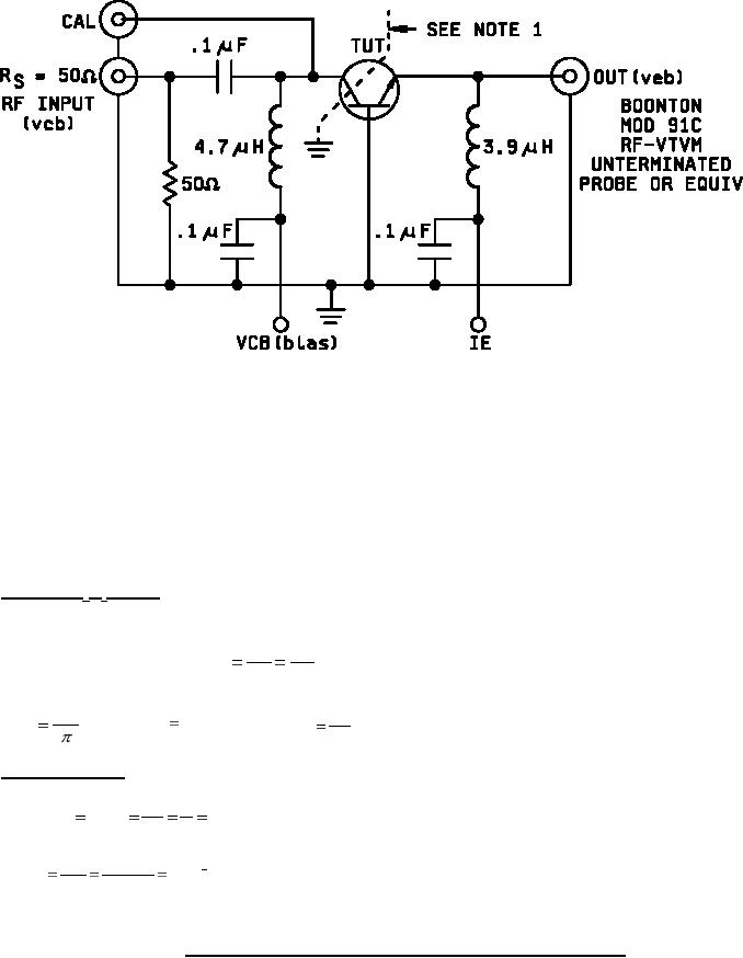
NOTE 1: External interlead shield to isolate the collector from the emitter and base leads.
PROCEDURE:
1. Connect 31.8 MHz source to input connect on test jig.
2. Connect RF voltmeter to "CAL" connector on test jig.
3. Adjust 31.8 MHz signal level so that 0.5 volts is read on RF voltmeter.
4. Remove the RF voltmeter from "CAL" connector and connect to "OUT" connector.
5. Insert TUT into socket and adjust bias.
6. Read output on RF voltmeter and compute rb'Cc from the following relationship:
rb'Cc:(psec) = 10 x Veb (millivolts)
Derivation of rb'Cc readout:
hrb set-up:
Veb
Veb
Set input (Vcb ) at 1.0 Volt; then
= meter reading.
hrb
1
Vcb
hrb ; therefore,
Veb .
(2 Xf )(rb 'Cc ) , also hrb
hrb
rb ' Cc
2f
Vcb
Sample: at 31.8 MHz
Veb
.1
Make h
.2 then
.2; hrb
rb
.5
Vcb
.2
hrb
9
rb 'Cc
1 x 10
x 1,000 p sec.
200 x106
2 Xf
(Other frequencies are treated in the same manner).
FIGURE 3. Collector-base time constant test circuit (an equivalent circuit may be used).
8
For Parts Inquires call Parts Hangar, Inc (727) 493-0744
© Copyright 2015 Integrated Publishing, Inc.
A Service Disabled Veteran Owned Small Business