MIL-PRF-19500/395K
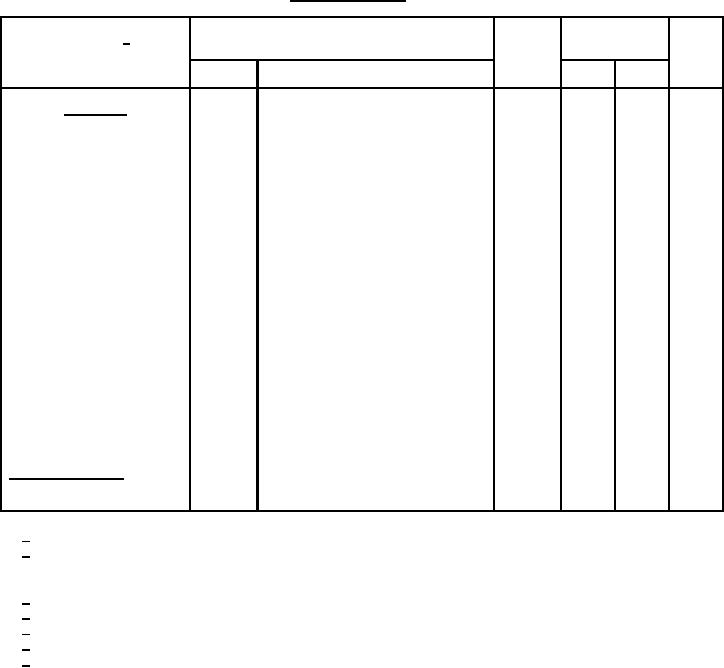
TABLE I. Group A inspection - Continued.
MIL-STD-750
Symbol
Limit
Unit
Inspection 1/
Method
Conditions
Min
Max
Subgroup 4
3306
Magnitude of common - emitter
2.5
6.0
VCE = 10 V dc; IC = 50 mA dc;
|hfe|
small-signal short-circuit forward
f = 100 MHz
current transfer ratio
Open circuit output capacitance
3236
VCB = 10 V dc, IE = 0,
9.0
pF
Cobo
100 kHz ≤ f ≤ 1 MHz
Input capacitance (output open
3240
80
pF
VEB = 0.5 V dc, IC = 0,
Cibo
100 kHz ≤ f ≤ 1 MHz
circuited)
Pulse response:
Delay response
3251
8.0
ns
Test condition A; VCC = 30 V dc,
td
VBE = 2 V dc, IC = 1.0 A dc,
IB1 = 100 mA dc, (see figure 4)
Rise time
3251
Test condition A; VCC = 30 V dc,
40
ns
tr
VBE = 2 V dc, IC = 1.0 A dc,
IB1 = 100 mA dc, (see figure 4)
Turn-off time
3251
Test condition A; VCC = 30 V dc,
60
ns
toff
IC = 1.0 A dc, IB1 = -IB2 = 100 mA dc,
(see figure 5)
Subgroups 5, 6 and 7
Not applicable
1/ For sampling plan, unless otherwise specified see MIL-PRF-19500.
2/ For resubmission of failed subgroup table I, double the sample size of the failed test or sequence of tests.
A failure in table I, subgroup 1 shall not require retest of the entire subgroup. Only the failed test shall be rerun
upon submission.
3/ Separate samples may be used.
4/ Not required for JANS devices.
5/ Not required for laser marked devices.
6/ This hermetic seal test is an end-point to temp-cycling in addition to electrical measurements.
7/ This test required for the following end-point measurements only: Group B, subgroups 3, 4, and 5 (JANS);
group B, see 4.4.2.2 herein, after each step (JAN, JANTX, and JANTXV); group C, subgroup 2 and 6,
group E, subgroup 1.
13
For Parts Inquires call Parts Hangar, Inc (727) 493-0744
© Copyright 2015 Integrated Publishing, Inc.
A Service Disabled Veteran Owned Small Business