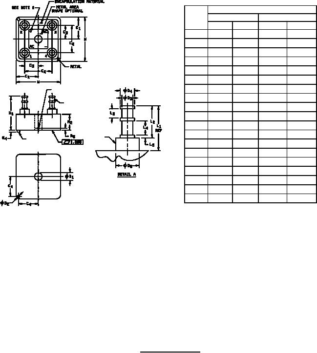
MIL-PRF-19500/446E
Dimensions
Ltr
Inches
Millimeters
Min
Max
Min
Max
C1
.552
.572
14.02
14.53
C2
.624
.760
15.85
19.30
C3
.312
.380
7.92
9.65
C4
.495
.512
12.57
13.00
D1
.189
.195
4.80
4.95
D2
.057
.067
1.45
1.70
D3
.108
.118
2.74
3.00
SEE NOTE 3
D4
.141
.151
3.58
3.84
SEE DETAIL
D5
.225
.260
5.72
6.60
H1
.690
1.060
17.53
26.92
H2
.300
.500
7.62
12.70
H3
.040
.060
1.02
1.52
SE
SE
NOTE
H4
.042
.062
1.07
1.57
NOTE
L1
.370
.560
9.40
14.22
L2
.307
.365
7.80
9.27
L3
.089
.099
2.26
2.52
L4
.132
.163
3.35
4.14
L5
.026
.036
0.66
0.91
W
1.104 1.144
28.04
29.06
NOTES:
1. Dimensions are in inches. Millimeters are given for general information only.
2. Polarity shall be marked on the terminal side of the device. Terminal numbers are for reference and do not have
to be marked on the bridge.
3. Point at which TC is read shall be in metal part of case as shown on drawing.
4. The locating pin shall be adjacent to the positive (+) terminal.
5. Insulating sleeve shall be alumina (AL2O3) composite material or equivalent.
6. The areas defined by the dimensions "L3" and "L4" are both acceptable for wire wrap and soldering.
7. In accordance with ASME Y14.5M, diameters are equivalent to x symbology.
FIGURE 1. Physical dimensions.
3
For Parts Inquires call Parts Hangar, Inc (727) 493-0744
© Copyright 2015 Integrated Publishing, Inc.
A Service Disabled Veteran Owned Small Business