MILŁPRFŁ19500/114H
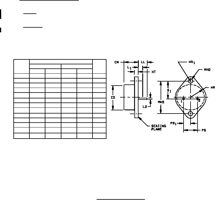
3.4 Interface and physical dimensions. The interface and physical dimensions shall be as specified in
MILŁPRFŁ19500 and herein. Current density of internal conductors shall be as specified in MILŁPRFŁ19500.
3.4.1 Polarity. Standard units (B) shall have the anode connected to the case. The two pins shall be connected
internally. Reversed units (RB) shall have the cathode connected to the case.
3.4.2 Lead finish. Lead finish shall be solderable in accordance with MILŁPRFŁ19500, MILŁSTDŁ750, and herein.
Where a choice of lead finish is desired, it shall be specified in the acquisition document (see 6.2).
Dimensions
Notes
Ltr
Inches
Millimeters
Min
Max
Min
Max
CH
.270
.380
6.86
9.65
LD
.048
.053
0.97
1.35
CD
.875
22.23
PS
.420
.440
10.67
11.18
2
PS1
.205
.225
5.21
5.72
2
HT
.060
.135
1.52
3.43
LL
.312
.500
7.92
12.70
L1
.050
1.27
MHD
.151
.165
3.84
4.09
MHS
1.177
1.197
29.90
30.40
HR
.495
.525
12.57
13.34
HR1
.131
.188
3.33
4.78
S1
.655
.675
16.64
17.15
NOTES:
1. Dimensions are in inches. Millimeters are given for general information only.
2. These dimensions should be measured at points .050 inch (1.27 mm) +.005 inch (+0.13 mm) Ł.000
inch (Ł0.00 mm) below seating plane.
3. The seating plane of the header shall be flat within .001 inch (0.03 mm) concave to .004 inch (0.10 mm)
convex .001 inch (0.03 mm) concave to .006 inch (0.15 mm) convex overall.
4. Pins 1 and 2 are internally connected with an internal jumper.
5. Devices with RB suffix (reverse polarity) have the cathode internally connected to the case.
6. In accordance with ASME Y14.5M, diameters are equivalent to Φx symbology.
FIGURE 1. Physical dimensions (TO-3).
3
For Parts Inquires call Parts Hangar, Inc (727) 493-0744
© Copyright 2015 Integrated Publishing, Inc.
A Service Disabled Veteran Owned Small Business