MILPRF19500/114H
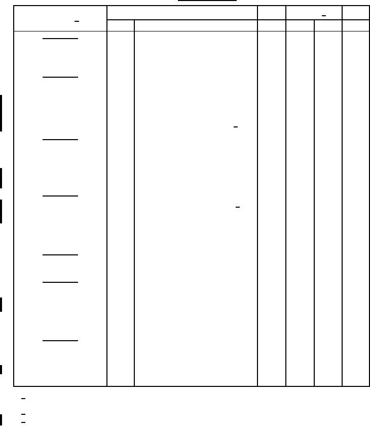
TABLE I. Group A inspection.
Symbol
Limits 2/
Unit
Inspection 1/
Method
Conditions
Min
Max
Subgroup 1
Visual and mechanical
2071
Inspection
Subgroup 2
V dc
Forward voltage
4011
1.5
IF = 10 A dc
VF
µA dc
Reverse current
4016
Col 11
VR = column 10 of table III;
IR1
DC method (see 4.5.7)
V dc
Regulator voltage
4022
Col 2
Col 3
IZ = column 4 of table III herein 3/
VZ
Subgroup 3
TA = 150°C
High temperature
operation:
µA dc
Reverse current
4016
Col 13
VR = column 10 of table III herein;
IR2
DC method
Subgroup 4
ohms
Small-signal breakdown
4051
Z
Col 5
IZ = column 4 of table III herein; 3/
impedance
Isig = 10 percent of IZ
ohms
Knee impedance
4051
Col 6
IZK = 5 mA dc;
ZK
Isig = 10 percent of IZ
Subgroup 5
Not applicable
Subgroup 6
Surge current (see 4.5.1)
4066
JANS level only
IZSM = column 9 of table III herein
End point electrical
See table I, subgroup 2 herein
measurements
Subgroup 7
V dc
Voltage regulation
JANS level only n = 22, c = 0
Col 8
VZ(reg)
(see 4.5.2)
%/°C
αVZ
4071
Col 12
Temperature coefficient of
IZ = column 4 of table III herein;
regulator voltage (see 4.5.4)
T1 = 30 ±3°C, T2 = T1 +100°C
1/
For JANS, all devices required by the specified sampling plan shall be subjected to subgroups 2, 3, and 4
combined.
Column references are for table III herein.
2/
During this test, the TC of the diode shall be equal to 30 ±3°C.
3/
8
For Parts Inquires call Parts Hangar, Inc (727) 493-0744
© Copyright 2015 Integrated Publishing, Inc.
A Service Disabled Veteran Owned Small Business