MIL-PRF-19500/315G
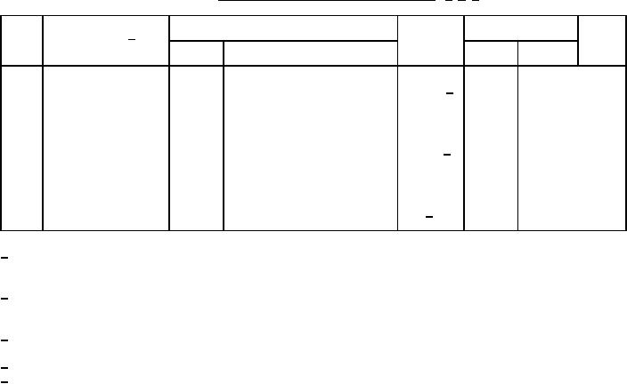
* TABLE III. Groups B, C, and E delta measurements. 1/ 2/ 3/
MIL-STD-750
Symbol
Limits
Unit
Step
Inspection 4/
Method
Conditions
Min
Max
1.
Collector to base
100 percent of
3036
ICBO1 5/
Bias condition D; VCB = 80 V dc
cutoff current
initial value or 100
nA dc, whichever is
greater.
3076
2.
Forward current
+20 percent, -10
hFE2 5/
VCE = 2 V dc; IC = 1 A dc;
transfer ratio
percent change
pulsed (see 4.5.1)
from initial reading.
3.
Collector to emitter
50 mV dc change
3071
VCE(sat)1
IC = 1.0 A dc; IB = 0.1 A dc;
voltage (saturated)
from previously
5/
pulsed (see 4.5.1)
measured value.
1/ The delta measurements for table E-VIa (JANS) of MIL-PRF-19500 are as follows:
a. Subgroup 4, see table III herein, steps 1, 2, and 3.
b. Subgroup 5, see table III herein, steps 1, 2, and 3.
2/ The delta measurements for table E-VIb (JANTX and JANTXV) of MIL-PRF-19500 are as follows:
a. Subgroup 3, see table III herein, step 2.
b. Subgroup 6, see table III herein, steps 1 and 2.
3/ The delta measurements for table E-VII of MIL-PRF-19500 are as follows: Subgroup 6, see table III herein, steps
1 and 2 (JANS) and step 2 (JAN, JANTX, and JANTXV).
4/ See MIL-PRF-19500 for sampling plan.
5/ Devices which exceed the group A limits for this test shall not be accepted.
15
For Parts Inquires call Parts Hangar, Inc (727) 493-0744
© Copyright 2015 Integrated Publishing, Inc.
A Service Disabled Veteran Owned Small Business