MIL-PRF-19500/404C
TYPE 1N5603
TYPES 1N5600 and 1N5597
Dimension
Dimensions
Ltr
Notes
Ltr
Notes
Inches
Millimeters
Inches
Millimeters
Min
Max
Min
Max
Min
Max
Min
Max
A
.970
1.020
24.64
25.91
14
A
.73
.83
18.54
21.08
14
B
.050
.080
1.27
2.03
B
---
.080
---
2.03
C
.307
.317
7.80
8.05
7, 12
C
.240
.264
6.10
6.71
6, 10, 12
.318
.400
8.08
10.16
9, 11, 12
.265
.400
6.73
10.16
8, 12
C1
C1
φD
φD
3.450
3.650
87.63
92.71
1.85
1.95
46.99
49.53
φD1
φD1
.95
1.250
24.13
31.75
11, 13
.57
.67
14.48
17.02
13
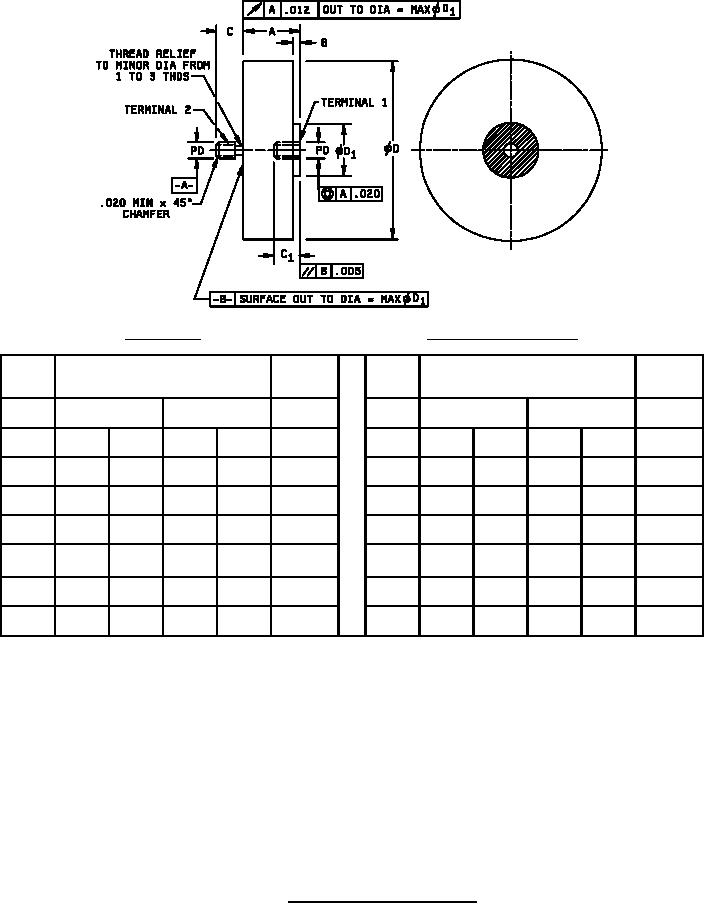
NOTES:
1. Dimensions are in inches.
2. Metric equivalents are given for general information only.
3. Surface roughness of all external metal surfaces except threaded areas shall not exceed 63 microinches rms.
4. Threaded portions of the assembly shall be in accordance with NBS handbook H28 (screw thread standards for federal services,
1957). The maximum pitch diameter of plated threads shall be the basic pitch diameter.
5. All marking shall be on cathode side of module.
6. Threaded stud .250-28UNF-2A.
7. Threaded stud .375-24UNF-2A.
8. Threaded insert .250-28UNF-2B.
9. Threaded insert .375-24UNF-2B.
10. Cathode connected to terminal 2.
11. Cathode connected to terminal 1.
12. Full length thread.
13. Metal terminal contact surface.
14. Module contour within dimension A is not specified.
FIGURE 1. Semiconductor device, diode module.
3
For Parts Inquires call Parts Hangar, Inc (727) 493-0744
© Copyright 2015 Integrated Publishing, Inc.
A Service Disabled Veteran Owned Small Business