MIL-PRF-19500/589A
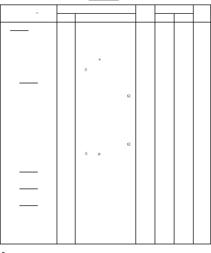
TABLE I. Group A inspection - Continued.
Inspection 1/
MIL-STD-750
Symbol
Limits
Unit
Method
Conditions
Min
Max
Subgroup 3 - Continued
State collector to emitter
3405
2.85
V
VGE = 15 V; IC = IC2
VCE(on)3
on-state voltage
pulsed (see 4.5.1)
Forward voltage
4011
1.5
V
VG = 0; IC = IC2
VF
Low temperature operation:
TC = TJ = -55 C
Gate to emitter voltage
3403
6.5
V dc
VCE
VGE; IC = 0.25 mA
VGE(th)
(threshold)
Subgroup 4
Switching time test
3477
IC = rated IC2; VGE = 15 V dc
VCC = 0.8 X VBR(CES); RG = 2.0
Turn-on delay time
50
ns
td(on)
Rise time
75
ns
tr
Turn-off delay time
300
ns
td(off)
Fall time
210
ns
tf
Total switching losses
3477
2.8
mJ
Etotal
IC = rated IC2; VGE = 15 V dc
VCC = 0.8 X VBR(CES); RG = 2.0
Reverse recovery time
3473
100
ns
di/dt
200 A/ s, IF = IC2
trr
Maximum reverse current
10
A
IRM
Subgroup 5
Not applicable
Subgroup 6
Not applicable
Subgroup 7
Gate charge
3471
On-state gate charge
140
nC
Qg(on)
Gate to emitter charge
35
nC
Qge
Gate to collector charge
70
nC
Qgc
1/ For sampling plan, see MIL-PRF-19500.
11
For Parts Inquires call Parts Hangar, Inc (727) 493-0744
© Copyright 2015 Integrated Publishing, Inc.
A Service Disabled Veteran Owned Small Business