MIL-PRF-19500/589A
4.5.2 Thermal resistance.
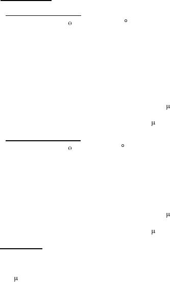
4.5.2.1 Thermal resistance for IGBT. Thermal resistance measurements shall be performed in accordance with method 3103 of MIL-
STD-750. The maximum limit of R JC(max) shall be 0.64 C /W. The following parameter measurements shall apply:
Measuring current (IM) ............................................. 10 mA.
a.
Collector heating current (IH).................................... 4 A minimum.
b.
Heating time (tH)....................................................... Steady-state (see MIL-STD-750, method 3103, for definition).
c.
Collector-emitter heating voltage (VH) ...................... 25 V minimum.
d.
Measurement time delay (tMD) ................................. 30 to 60 s.
e.
Sample window time (tSW) ....................................... 10 s maximum.
f.
4.5.2.2 Thermal resistance for diode. Thermal resistance measurements shall be performed in accordance with method 3101 of MIL-
STD-750. The maximum limit of R JC(max) shall be 1.2 C/W. The following parameter measurements shall apply:
Measuring current (IM) ............................................. 10 mA.
a.
Collector heating current (IH).................................... 15 A minimum.
b.
Heating time (tH)....................................................... Steady-state (see MIL-STD-750, method 3103, for definition).
c.
Measurement time delay (tMD) ................................. 30 to 60 s.
d.
Sample window time (tSW) ....................................... 10 s maximum.
e.
4.5.3 Gate stress test.
VGE = 30 V minimum.
t = 250 s minimum.
8
For Parts Inquires call Parts Hangar, Inc (727) 493-0744
© Copyright 2015 Integrated Publishing, Inc.
A Service Disabled Veteran Owned Small Business