MIL-PRF-19500/555L
1.3 Maximum ratings. Continued.
(1) Derate linearly 0.16 W/°C for TC > +25°C for "non-U" suffix versions, 0.11 W/°C for TC > +25°C for "U" suffix
versions.
(2) See figure 8, thermal impedance curves.
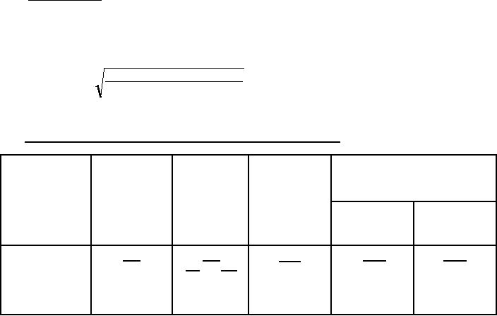
(3) The following formula derives the maximum theoretical ID limit. ID is also limited by package and internal wires
and may be limited due to pin diameter.
TJ (max)-TC
ID=
RθJC x( RDS (on) atTJ (max))
(4) See figure 9, maximum drain current graph.
(5) IDM = 4 ID1; ID1 as calculated in footnote (3).
1.4 Unless otherwise specified, primary electrical characteristics at TC = +25°C.
Type
Min V(BR)DSS
VGS(th)1
Max IDSS1
Max rDS(on) (1)
VDS ≥ VGS
VGS = 0
VGS = 0
VGS = 10 V dc
ID = 1.0 mA dc
ID = ID2
ID = 0.25 mA
TJ = +25°C
TJ = +150°C
VDS
= 80 percent
of rated VDS
µA dc
V dc
V dc
Ohms
Ohms
Min
Max
2N6788, 2N6788U
100
0.30
0.60
2.0
4.0
25
2N6790, 2N6790U
200
0.80
1.80
2.0
4.0
25
2N6792, 2N6792U
400
1.80
4.50
2.0
4.0
25
2N6794, 2N6794U
500
3.00
7.50
2.0
4.0
25
(1) Pulsed (see 4.5.1).
2
For Parts Inquires call Parts Hangar, Inc (727) 493-0744
© Copyright 2015 Integrated Publishing, Inc.
A Service Disabled Veteran Owned Small Business