MIL-PRF-19500/627C
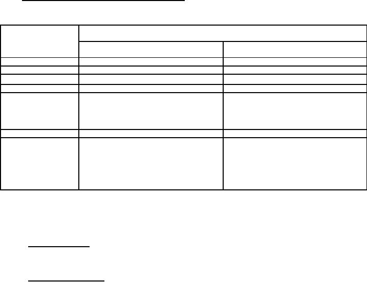
4.3 Screening (JANS, JANTX, AND JANTXV levels only). Screening shall be in accordance with table E-IV of
MIL-PRF-19500, and as specified herein. The following measurements shall be made in accordance with table I
herein. Devices that exceed the limits of table I herein shall not be acceptable.
Screen (see table E-IV
Measurement
of MIL-PRF-19500)
JANS level
JANTXV and JANTX level
(1) 3c
Thermal impedance (see 4.3.1)
Thermal impedance (see 4.3.1)
5
Not applicable
Not applicable
9
Not required
Required IR1 and VFM1
Method 1038 of MIL-STD-750, condition A
Method 1038 of MIL-STD-750, condition A
10
IR1 and VFM1, ĆIR1 ≤ 100 percent of initial
11
IR1 and VFM1
reading or ±100 nA dc (± 200 nA dc for
1N6625), whichever is greater. Ć VFM1 ≤
±0.05 V dc
12
Required, see 4.3.2
Required, see 4.3.2
(2) 13
Subgroups 2 and 3 of table I herein:
Subgroup 2 of table I herein:
ĆIR1 ≤ 100 percent of initial reading or ±100
ĆIR1 ≤ 100 percent of initial reading or ±100
nA dc (±200 nA dc for 1N6625), whichever is
nA dc (±200 nA dc for 1N6625), whichever is
greater.
greater.
Ć VFM1 ≤ ±0.05 V dc. Scope display
Ć VFM1 ≤ ±0.05 V dc. Scope display
evaluation (see 4.5.4)
evaluation (see 4.5.4)
(1) Thermal impedance shall be performed any time after sealing provided temperature cycling is performed in
accordance with MIL-PRF-19500, screen 3 prior to this thermal test.
(2) ZθJX is not required in screen 13, if already previously performed.
4.3.1 Thermal impedance. The thermal impedance measurements shall be performed in accordance with method
3101, as applicable, of MIL-STD-750 using the guidelines in that method for determining IM, IH, tH, and K factor. See
table II, group E, subgroup 4 herein.
4.3.2 Power burn-in conditions. Power burn-in conditions are as follows (see 4.5.3 and 4.5.3.1), TA = +55șC
maximum. Test conditions shall be in accordance with method 1038 of MIL-STD-750, condition B. Adjust IO to
achieve the required TJ. Use method 3100 of MIL-STD-750 to measure TJ. TJ = +115șC minimum and +150șC
maximum.
5
For Parts Inquires call Parts Hangar, Inc (727) 493-0744
© Copyright 2015 Integrated Publishing, Inc.
A Service Disabled Veteran Owned Small Business