MIL-PRF-19500/304E
Dimensions
Ltr
Notes
Inches
Millimeters
Min
Max
Min
Max
CD
.424
10.77
CH
.405
10.29
.020
.065
0.51
1.65
9
CH1
G
.060
1.52
HF
.424
.437
10.77
11.10
HT
.075
.175
1.90
4.44
OAH
.800
20.32
OM
.163
.189
4.14
4.80
SL
.422
.453
10.72
11.50
SP
5, 6, 7, 8
T
.060
1.52
TD
.250
6.35
NOTES:
1. Dimensions are in inches.
2. Millimeters are given for general information only.
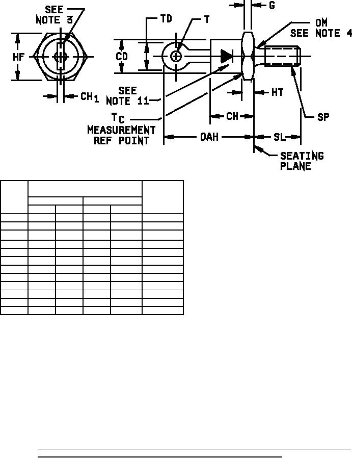
3. Angular orientation of this terminal is undefined. Square or radius on end of terminals is optional.
4. Diameter variations within these limits are permitted.
5. The ANSI thread reference is 0.190-32 UNF-2A.
6. Max pitch diameter of plated threads shall be basic pitch diameter 0.169 inch (4.29 mm) reference FED-STD-
H28 (Screw Thread Standards for Federal Services.)
7. Units must not be damaged by torque of 15 inch-pounds applied to 0.190-32 UNF-2B nut assembled on
thread.
8. Complete threads to extend to within 0.078 inch (1.98 mm) of the seating plane.
9. Terminal-end shape is unrestricted.
10. Reversed (anode to stud) units shall be marked with an "R" following the last digit in the type number.
11. Forward polarity (cathode to stud) marking is shown.
FIGURE 2. Physical dimensions of non-isolated types: 1N3890, 1N3890A, 1N3891, 1N3891A, 1N3893, 1N3893A,
1N3890R, 1N3890AR, 1N3891R, 1N3891AR, 1N3893R, and 1N3893AR (DO-4).
4
For Parts Inquires call Parts Hangar, Inc (727) 493-0744
© Copyright 2015 Integrated Publishing, Inc.
A Service Disabled Veteran Owned Small Business