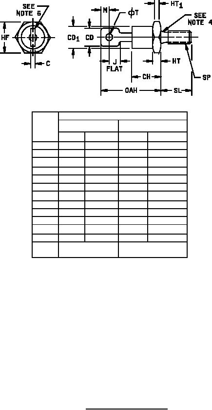
MIL-PRF-19500/308D
Dimensions
Ltr
Inches
Millimeters
Min
Max
Min
Max
C
0.030
0.080
0.76
2.03
CD
0.250
0.375
6.35
9.52
0.667
16.94
CD1
CH
0.450
11.43
HF
0.669
0.688
16.99
17.48
HT
0.115
0.200
2.93
5.08
0.060
1.53
HT1
J
0.156
3.97
M
0.030
0.77
OAH
0.750
1.000
19.05
25.40
∅T
0.140
0.175
3.56
04.44
SL
0.422
0.453
10.72
11.50
SP
.250-28 UNF-2A
6.35-28 UNF-2A
THD NF optional
THD NF optional
NOTES:
1. Dimensions are in inches.
2. Metric equivalents are given for general information only.
3. Units must not be damaged by torque of 30 inch-pounds applied to 0.250-28 UF-2B nut assembled on
thread.
4. Diameter of unthreaded portion 0.249 inch (6.32 mm) max and 0.220 inch (5.59 mm) minimum.
5. Complete threads to extend to within 2.5 threads of seating plane.
6. Angular orientation for this terminal is underlined, however the major surfaces over dimension CD shall
be flat and the minimum distance from the hole to any point on the periphery shall be 0.030 inch (0.76
mm) outside dimension J.
7. Max pitch diameter of plated threads shall be basic pitch diameter 0.2268 inch (5.76 mm) reference FED-
STD-H28.
8. (Screw Thread Standards for Federal Services.)
9. A chamfer or undercut on one or both ends of the hex portion is optional: Minimum bas diameter at
seating plane. 0.600 inch (15.24 mm).
10. Reversed (anode to stud) units shall be marked with an R following the last digit in the type number.
FIGURE 1. Physical dimensions (DO-5).
2
For Parts Inquires call Parts Hangar, Inc (727) 493-0744
© Copyright 2015 Integrated Publishing, Inc.
A Service Disabled Veteran Owned Small Business