MIL-PRF-19500/348F
* 4.4.3.3 Group C sample selection. Samples for steps in group C shall be chosen at random from any inspection lot
containing the intended package type and lead finish procured to the same specification which is submitted to and
passes table I tests for conformance inspection. When the final lead finish is solder or any plating prone to oxidation
at high temperature, the samples for C6 life test may be pulled prior to the application of final lead finish. Testing of a
subgroup using a single device type enclosed in the intended package type shall be considered as complying with the
requirements for that subgroup.
* 4.4.4 Group E inspection. Group E inspection shall be conducted in accordance with the conditions specified for
subgroup testing in appendix E, table IX of MIL-PRF-19500 and as specified in table II herein. Electrical
measurements (end-points) shall be in accordance with table I, subgroup 2 herein. Delta measurements shall be in
accordance with the applicable steps of 4.5.3.
4.5 Method of inspection. Methods of inspection shall be as specified in the appropriate tables and as follows.
4.5.1 Pulse measurements. Conditions for pulse measurement shall be as specified in section 4 of MIL-STD-750.
4.5.2 Input capacitance. This test shall be conducted in accordance with method 3240 of MIL-STD-750, except the
output capacitor shall be omitted.
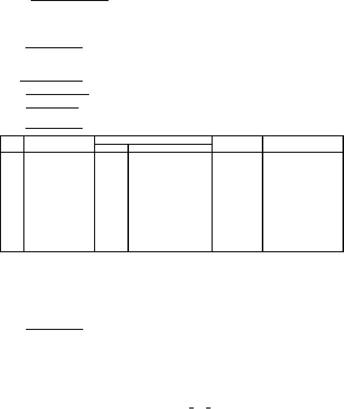
* 4.5.3 Delta requirements. Delta requirements shall be as specified below: (1) (2) (3) (4) (5)
Step
Inspection
MIL-STD-750
Symbol
Limit
Method
Conditions
ĆICBO1
100 percent of initial
3036
Bias condition D;
1.
Collector to base
value or 50 nA dc,
VCB = 30 V dc
cutoff current
(1)
whichever is greater.
ĆVCE(SAT)2
50 mV dc change from
2.
Collector to emitter
3071
IC = 500 mA dc;
initial value.
voltage saturated
IB = 50 mA dc; pulsed
(see 4.5.1)
ĆhFE2
25 percent change from
3.
Forward-current
3076
VCE = 1.0 V dc;
initial value.
transfer ratio
IC = 500 mA dc; pulsed
(1)
(see 4.5.1)
(1) Devices which exceed the table I limits for this test shall not be accepted.
(2) The delta electrical measurements for subgroup 5, table VIa (JANS) of MIL-PRF-19500 are as follows: see 4.5.3,
steps 1, 2, and 3.
(3) The delta measurements for Group B (see 4.4.2.2. herein, JAN, JANTX and JANTXV) are as follows:
see 4.5.3, steps 1, 2 and 3.
(4) The delta electrical measurements for subgroup 6, table VII of MIL-PRF-19500 are as follows: see 4.5.3, step 3.
* (5) The delta measurements for table IX of MIL-PRF-19500 and table II herein are as follows: Subgroups 1 and 2,
see 4.5.3, all steps.
4.5.4 Thermal resistance. Thermal resistance measurements shall be conducted in accordance with method 3131
of MIL-STD-750. The following details shall apply:
a. Minimum collector current magnitude during power application shall be 160 mA dc for RΘJC and 32 mA dc for
RΘJA.
b. Collector to base voltage magnitude shall be 10 V dc.
c. Reference temperature measuring point shall be the case for RΘJC and ambient air for RΘJA.
d. Reference point temperature shall be selected with 25°C < TR < 35°C and recorded before test is started.
e. Mounting arrangement shall be with heat sink to case for RΘJC and without heat sink for RΘJA.
f. Maximum limits shall be RΘJC = 30°C/W and RΘJA = 175°C/W.
8
For Parts Inquires call Parts Hangar, Inc (727) 493-0744
© Copyright 2015 Integrated Publishing, Inc.
A Service Disabled Veteran Owned Small Business