MIL-PRF-19500/349J
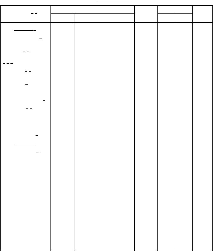
TABLE I. Group A inspection.
Inspection 1/ 2/
MIL-STD-750
Limit
Unit
Symbol
Method
Conditions
Min
Max
Subgroup 1 3/
Visual and mechanical 4/
2071
JAN, JANTX: n = 45 devices, c = 0
examination
JANTXV: n = devices, c = 0
n = 15 leads, c = 0
Solderability 4/ 5/
2026
n = 15 devices, c = 0
1022
Resistance to solvents
4/ 5/ 6/
Temp cycling 4/ 5/
1051
Test condition C, 25 cycles.
n = 22 devices, c = 0
Hermetic seal 5/
1071
n = 22 devices, c = 0
Fine leak
Gross leak
Table I, subgroup 2
Electrical measurements 5/
Precondition TA = +250�C at
Bond strength 4/ 5/
2037
t = 24 hrs or
TA = 300�C at t = 2 hrs
n = 11 wires, c = 0
Decap internal visual
2075
n = 4 devices, c = 0
(design verification) 4/
Subgroup 2
�C/W
Thermal impedance 7/
3131
See 4.3.2
ZθJX
Bias condition D, IC = 100 �A dc
Breakdown voltage collector
3001
V(BR)CBO
to base
2N3506
60
V dc
2N3507
80
V dc
Bias condition D, IE = 10 �A dc
Breakdown voltage emitter
3026
5
V dc
V(BR)EBO
to base
Breakdown voltage collector
3011
Bias condition D, IC = 10 mA dc,
V(BR)CEO
to emitter
pulsed (see 4.5.1)
2N3506
40
V dc
2N3507
50
V dc
�A dc
Collector to emitter cutoff
3041
1
Bias condition A, VEB = 4 V dc
ICEX1
current
2N3506
VCE = 40 V dc
2N3507
VCE = 60 V dc
Forward-current transfer
3076
VCE = 1 V dc, IC = 500 mA dc,
hFE1
ratio
pulsed (see 4.5.1)
2N3506
50
250
2N3507
35
175
See footnotes at the end of table
11
For Parts Inquires call Parts Hangar, Inc (727) 493-0744
© Copyright 2015 Integrated Publishing, Inc.
A Service Disabled Veteran Owned Small Business