MIL-PRF-19500/415A
Dimension
Ltr
Inches
Millimeters
Notes
Min
Max
Min
Max
A1
.270
6.86
CD
.570
.610
14.48
15.49
CD1
17.45
.610
.687
15.49
CH
.325
.460
8.26
11.68
HF
.667
.687
16.94
17.45
8
HT
.090
.150
2.29
3.81
OAH
.640
.875
16.26
22.22
6
TO-61
PS
.340
.415
8.64
10.54
PS1
.170
.213
4.32
5.41
3
SL
.422
.455
10.72
11.56
SU
.090
2.29
T
.047
.072
1.19
1.83
7, 10
.046
.077
1.17
1.96
T1
UD
.220
.249
5.59
6.32
NOTES:
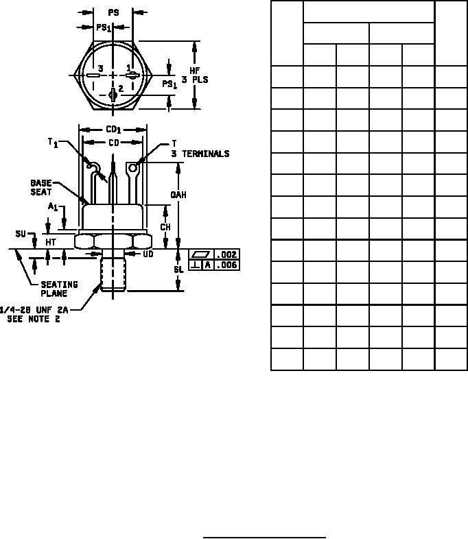
1. Dimensions are in inches. Millimeters are given for general information only.
2. See NSB Handbook H28, "Screw-Thread Standards for Federal Services".
3. Lead spacing measured at seat only.
4. Position of leads in relation to hex is not controlled.
5. Maximum recommended mounting torque 20 in-lb.
6. All three leads.
7. Two leads. (Base and emitter).
8. All three locations.
9. In accordance with ASME Y14.5M, diameters are equivalent to φx symbology.
10. The collector shall be electrically connected to the case.
11. Pin 1: emitter, pin 2: base, pin 3: collector.
FIGURE 1. Physical dimensions (TO-61).
3
For Parts Inquires call Parts Hangar, Inc (727) 493-0744
© Copyright 2015 Integrated Publishing, Inc.
A Service Disabled Veteran Owned Small Business