MIL-PRF-19500/452J
Dimensions
Symbol
Inches
Millimeters
Min
Max
Min
Max
A
.0280
.0320
.711
.813
B
.0080
.0100
.203
.254
C
.0104
.0106
.264
.269
D
.0019
.0021
.048
.053
E
.0054
.0056
.137
.142
F
.0020
.0040
.050
.102
G
.0280
.0320
.711
.813
H
.0030
.0050
.076
.127
J
.0030
.0050
.076
.127
K
.0209
.0211
.531
.536
L
.0080
.0100
.203
.254
M
.0104
.0106
.264
.269
N
.0059
.0061
.150
.155
Backside must be electrically isolated
to ensure proper performance.
Design data
Metallization:
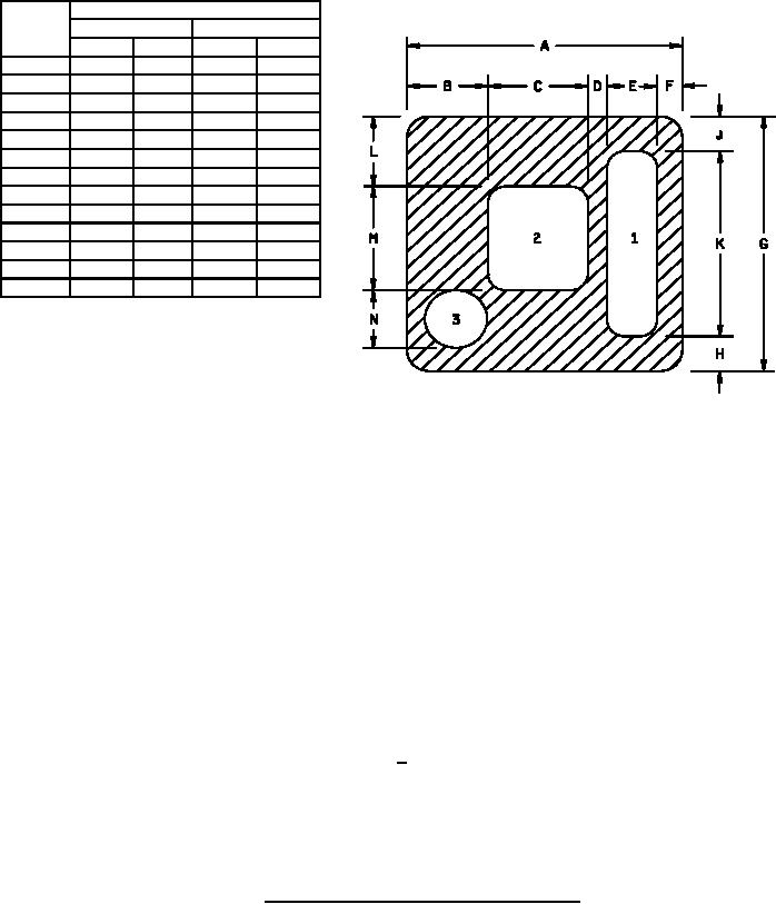
Top: 1 (Cathode)
Al
Circuit layout data:
2 (Anode)
Al
For zener operation, cathode must be
operated positive with respect to anode.
3 (Test pad)
Al
Test pad is for wire bond evaluation only.
No electrical contact is made with test pad.
Back:
Au
Al thickness
25,000Ĺ minimum.
Gold thickness
4,000Ĺ minimum.
Chip thickness
.010 inch (0.25 mm) ±0.002 inch (+0.05 mm).
NOTES:
1. Dimensions are in inches unless otherwise indicated.
2. Millimeters are given for general information only.
3. In accordance with ASME Y14.5M, diameters are equivalent to x symbology.
FIGURE 3. JANHC and JANKC (A-version) die dimensions.
5
For Parts Inquires call Parts Hangar, Inc (727) 493-0744
© Copyright 2015 Integrated Publishing, Inc.
A Service Disabled Veteran Owned Small Business