MIL-PRF-19500/455K
NOTES:
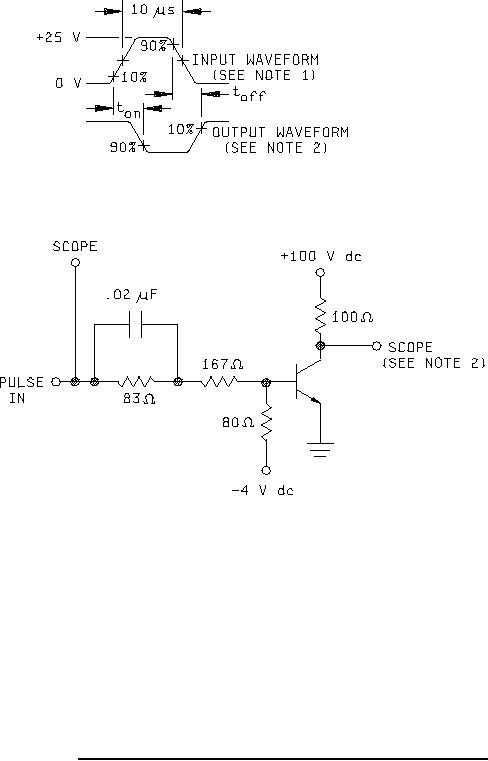
1. The input waveform is supplied by a pulse generator with the following characteristics: tr ≤ 15 ns, tf ≤ 15 ns,
Zout = 50 ohm, PW = 10 µs, duty cycle ≤ 2 percent.
2. Output waveforms are monitored on an oscilloscope with the following characteristics: tr ≤ 15 ns,
Zin ≥ 10 MΩ, Cin ≤ 11.5 pF.
3. Resistors shall be noninductive types.
4. The dc power supplies may require additional bypassing in order to minimize ringing.
5. The input pulse voltages and supply voltages (-4 V dc and +100 V dc) are nominal and shall be adjusted to
obtain IB1 = - IB2 = 50 mA and IC = 1 A.
6. An equivalent circuit may be used.
7. 0.02 µF capacitor may be removed during voltage adjustments.
FIGURE 17. Pulse response test circuit for types 2N5665, 2N5667, and 2N5667S.
32
For Parts Inquires call Parts Hangar, Inc (727) 493-0744
© Copyright 2015 Integrated Publishing, Inc.
A Service Disabled Veteran Owned Small Business