MIL-PRF-19500/474G
Inches
Millimeters
Symbol
Notes
Min
Max
Min
Max
BL
.255
.278
6.48
7.06
BL1
.288
7.32
2
BW
.194
.200
4.93
5.08
CH
.045
.095
1.14
2.41
LL
.265
.290
6.73
7.37
LL1
.724
.780
18.39 19.81
LO2
.020
.025
0.51
0.64
4
LS
.030 TP
0.76 TP
3, 5
LT
.004
.006
0.10
0.15
6
LU
.210
5.33
2
LW
.010
.019
0.25
0.48
6
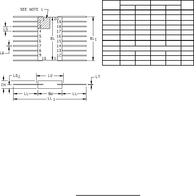
NOTES:
1. Index area: A notch or a pin 1 identification mark shall be located adjacent to pin 1 and shall be within the
shaded area limited by pin 3 and package centerline. The manufacturer's identification shall not be used as a
pin 1 identification mark.
2. This dimension allows for off-center lid, meniscus, and glass overrun.
3. The true position pin spacing is located within ±.005 inch (0.13 mm) of its true longitudinal position relative to
pins 1 and 20.
4. Dimension LO2 shall be measured at the point of exit of the lead from the body.
5. Eighteen spaces.
6. All leads: Dimensions are pre-solder dip.
7. Dimensions are in inches. Millimeters are given for general information only.
FIGURE 6. Physical dimensions for type 1N6496.
8
For Parts Inquires call Parts Hangar, Inc (727) 493-0744
© Copyright 2015 Integrated Publishing, Inc.
A Service Disabled Veteran Owned Small Business