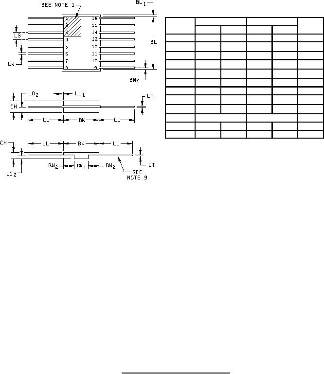
MIL-PRF-19500/474G
Inches
Millimeters
Symbol
Notes
Min
Max
Min
Max
BL
.370
.400
9.40
10.16
BL1
.020
0.51
2
BW
.245
.260
6.22
6.60
BW1
.015
0.38
BW2
0.030
0.76
CH
.045
.095
1.14
2.41
LL
.250
.370
6.35
9.40
LL1
.015
0.38
LO2
.025
.040
0.64
1.02
4
LS
.050 BSC
1.27 BSC
3, 5
LT
.003
.008
0.08
0.20
7
LW
.015
.019
0.38
0.48
7
NOTES:
1. This package is inactive and shall be replaced with the package on figure 8.
2. Index area: A notch or a pin 1 identification mark shall be located adjacent to pin 1 and shall be within
the shaded area limited by pin 3 and package centerline. The manufacturer's identification shall not be
used as a pin 1 identification mark.
3. This dimension allows for off-center lid, meniscus, and glass overrun.
4. The true position pin spacing is located within ±.005 inch (0.13 mm) of its true longitudinal position
relative to pins 1 and 16.
5. Dimension LO2 shall be measured at the point of exit of the lead from the body.
6. Fourteen spaces.
7. All leads: Dimensions are pre-solder dip.
8. Dimensions are in inches. Millimeters are given for general information only.
9. If this configuration is used, no organic or polymeric materials shall be molded to the bottom of the
package to cover the leads.
FIGURE 7. Physical dimensions for type 1N6510.
9
For Parts Inquires call Parts Hangar, Inc (727) 493-0744
© Copyright 2015 Integrated Publishing, Inc.
A Service Disabled Veteran Owned Small Business