MIL-PRF-19500/538G
Dimension
Ltr
Inches
Millimeters
Notes
Min
Max
Min
Max
A1
.270
6.86
CD
.570
.610
14.48
15.49
CD1
.610
.687
15.49
17.45
CH
.325
.460
8.26
11.68
HF
.667
.687
16.94
17.45
HT
.090
.150
2.29
3.81
OAH
.640
.875
16.26
22.22
4
TO-61
PS
.340
.415
8.64
10.54
3, 6
PS1
.170
.213
4.32
5.41
3, 6
SL
.422
.455
10.72
11.56
SU
.090
2.29
7
T
.047
.072
1.19
1.83
T1
.046
.077
1.17
1.96
UD
.220
.249
5.59
6.32
NOTES:
1.
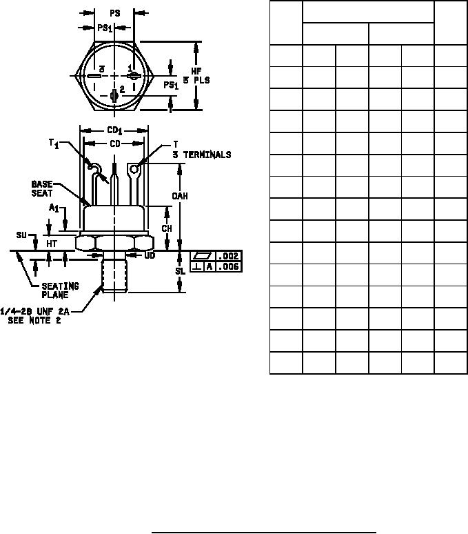
Dimensions are in inches, millimeters are given for general information only.
2.
See NSB Handbook H28, "Screw-Thread Standards for Federal Services".
3.
The orientation of the terminals in relation to the hex flats is not controlled.
4.
All three terminals.
5.
The case temperature may be measured anywhere on the seating plane within .125 inch (3.18 mm) of the
stud.
6.
Terminal spacing measured at the base seat only.
7.
This dimension applies to the location of the center line of the terminals.
8.
Terminal - 1, emitter; terminal - 2, base; terminal - 3, collector. All leads are isolated from the case.
In accordance with ASME Y14.5M, diameters are equivalent to φx symbology.
9.
FIGURE 2. Physical dimensions (TO-61) for 2N6691 and 2N6693.
4
For Parts Inquires call Parts Hangar, Inc (727) 493-0744
© Copyright 2015 Integrated Publishing, Inc.
A Service Disabled Veteran Owned Small Business