MIL-PRF-19500/559K
Dimensions
Dimensions
Symbol
Notes
Symbol
Notes
Inches
Millimeters
Inches
Millimeters
Min
Max
Min
Max
Min
Max
Min
Max
BH
.200
5.08
LS
.100 BSC
2.54 BSC
7, 11
LW
.014
.023
0.36
0.58
10
LL
.125
.200
3.18
5.08
.030
.150
3.81
.070
0.76
1.78
4, 10
LW1
LL1
LT
.008
.015
0.20
0.38
10
LO
.005
0.13
8
BL
.785
19.94
6
LO1
.098
2.49
8
BW
.220
.310
5.59
7.87
6
.015
.060
0.38
1.52
5
LO2
α
0°
15°
0°
15°
.290
.320
7.37
8.13
9
BW1
NOTES:
1. Dimensions are in inches.
2. Millimeters are given for general information only.
3. Index area: A notch or pin one identification mark shall be located adjacent to pin one and shall be
located within the shaded area shown. The manufacturer's identification shall not be used as a pin one
identification mark.
4. The minimum limit for dimension LW1 may be .023 inch (0.58 mm) for leads number 1, 7, 8, and 14 only.
5. Dimension LO2 shall be measured from the seating plane to the base plane.
6. This dimension allows for off-center lid, meniscus, and glass overrun.
7. The basic pin spacing is .100 inch (2.54 mm) between centerlines. Each pin centerline shall be located
within ±.010 inch (0.25 mm) of its exact longitudinal position relative to pins 1 and 14.
8. Applies to all four corners (leads number 1, 7, 8, and 14).
9. Lead center when α is 0 degrees. BW1 shall be measured at the centerline of the leads.
10. All leads.
11. Twelve spaces.
12. No organic or polymeric materials shall be molded to the bottom of the package to cover the leads.
13. In accordance with ASME Y14.5M, diameters are equivalent to φx symbology.
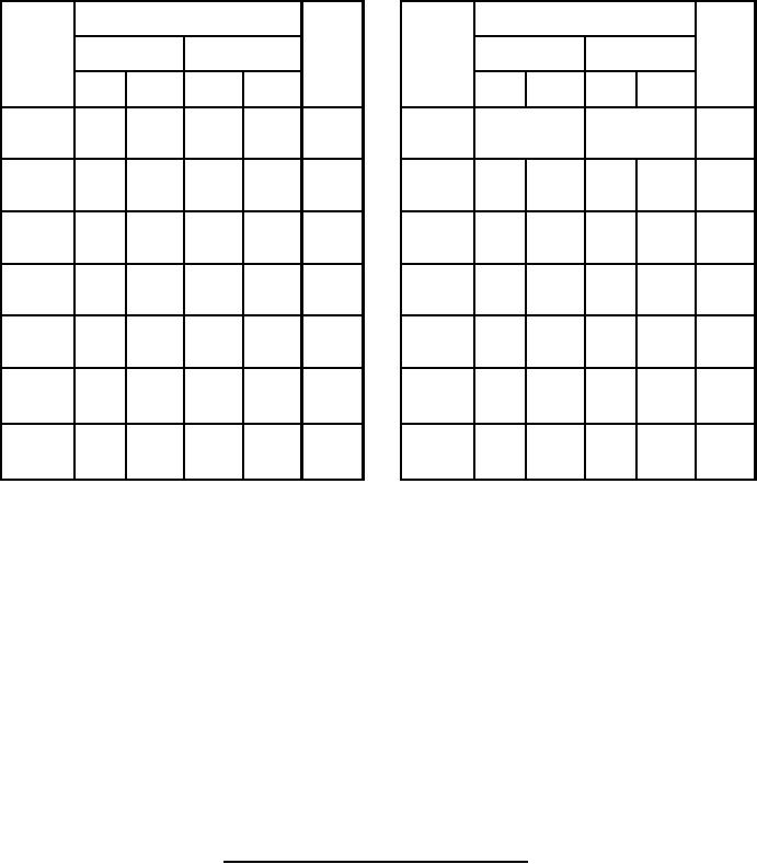
FIGURE 1. Dimensions and configuration for type 2N6989 - Continued.
4
For Parts Inquires call Parts Hangar, Inc (727) 493-0744
© Copyright 2015 Integrated Publishing, Inc.
A Service Disabled Veteran Owned Small Business