MILPRF19500/581C
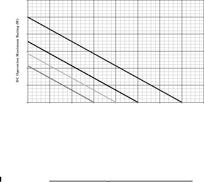
Temperature-Power Derating Curve
TA=25°C 2N4237, 2N4238, 2N4239
1.2
1
0.8
0.6
0.4
0.2
0
25
50
75
100
125
150
175
200
225
Ta (șC) (Ambient)
DC Operation
Thermal Resistance Junction to Ambient = 175șC/W
Note: Max Finish-Alloy Temp = 175.0șC
NOTES:
1. Top curve is thermal runaway loci and cannot be used as a derate design curve since it exceeds the
maximum ratings for this part. Operating under this curve using these mounting conditions assures the
device will not have a thermal runaway. This is the true inverse of the worst case thermal resistance value
extrapolated out to the thermal runaway point.
2. Derate design curve constrained by the maximum junction temperature (TJ ≤ 200°C) and power rating
specified. (See 1.3 herein.)
3. Derate design curve chosen at TJ ≤ 150°C, where the maximum temperature of electrical test is performed.
4. Derate design curve chosen at TJ ≤ 125°C, and 110°C to show power rating where most users want to limit
TJ in their application.
FIGURE 2. Temperature-power derating at TA for device types 2N4237, 2N4238, and 2N4239.
12
For Parts Inquires call Parts Hangar, Inc (727) 493-0744
© Copyright 2015 Integrated Publishing, Inc.
A Service Disabled Veteran Owned Small Business