MIL-PRF-19500/608D
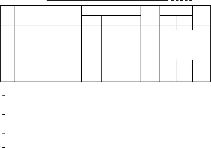
* TABLE II. Groups A, B, C, and E electrical end-point and delta measurements. 1/ 2/ 3/ 4/ 5/
MIL-STD-750
Limits
Step
Inspection
Symbol
Unit
Method
Conditions
Min
Max
ĆVF1
IF = 5 A (pk),
1.
Forward voltage
4011
±50 mV dc from initial
pulsed (see 4.5.1)
reading.
ĆIR1
VR = 45 V dc,
2.
Reverse current
4016
±25 µA dc or 100 percent
pulsed (see 4.5.1),
from initial reading,
dc method
whichever is greater.
°C/W
ZΘJC
3.
Thermal impedance
3101
See 4.3.2
1N6660CAT1, 1N6660DT1 (die 1)
1N6660CCT1, 1N6660DT1 (die 2)
1/ Each individual diode.
2/ The electrical measurements for table E-VIa (JANS) of MIL-PRF-19500 are as follows:
a. Subgroup 3, see table II herein, steps 1 and 2.
b. Subgroup 4, see table II herein, steps 1, 2, 3, 4, and 5.
c. Subgroup 5, see table II herein, steps 1, 2, 3, and 4.
3/ The electrical measurements for table E-VIb (JANTX and JANTXV) of MIL-PRF-19500 are as follows:
a. Subgroup 2, see table II herein, steps 1 and 2.
b. Subgroup 3, see table II herein, steps 1, 2, and 5.
c. Subgroup 6, see table II herein, steps 1 and 2.
4/ The electrical measurements for table E-VII of MIL-PRF-19500 are as follows:
a. Subgroups 2 and 3, see table II herein, steps 1 and 2.
b. Subgroup 6, see table II herein, steps 1, 2, and 5.
5/ Devices which exceed the table I, limits for this test shall not be accepted.
8
For Parts Inquires call Parts Hangar, Inc (727) 493-0744
© Copyright 2015 Integrated Publishing, Inc.
A Service Disabled Veteran Owned Small Business