MIL-PRF-19500/118L
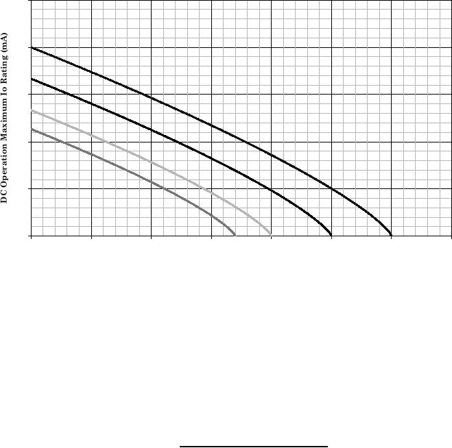
TEMemRerTture--CURRENT raERg TIurGeCURVE
TPEp A aURE Current De Dtin AC N v
1N483B, 1N5194, UR, US, 1N485B, 1N5195, RTSUS, 1N486B, 1N5196, UR, US
ALL PAUR,
250
200
150
100
50
0
25
50
75
100
125
150
175
200
DC Operation
Ta ((C))(AMBiIEntT)
TTC�CC (AmbIe N ) )
) (AMB E
A (
DC OPORAraOon
DC E peTIti N
Thermal Resistance Junction to Ambient = 275�C/W
THEθJA = RE5STW CE JUNCTION TO AMBIENT = 275C/W
RRMAL 27SI C/AN
NOTES:
1. This is the true inverse of the worst case thermal resistance value. All devices are capable of operating at TJ
specified on this curve. Any parallel line to this curve will intersect the appropriate power for the desired
maximum TJ allowed.
2. Derate design curve constrained by the maximum junction temperature (TJ 175C) and power/current rating
specified. (See 1.3 herein.)
3. Derate design curve chosen at TJ 150C, where the maximum temperature of electrical test is performed.
4. Derate design curves chosen at TJ , 125C, and 110C to show power/current rating where most users want to
limit TJ in their application.
FIGURE 4. Temperature-current derating graph.
13
For Parts Inquires call Parts Hangar, Inc (727) 493-0744
© Copyright 2015 Integrated Publishing, Inc.
A Service Disabled Veteran Owned Small Business