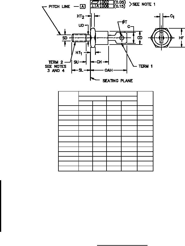
MILŁPRFŁ19500/124L
Dimensions
Symbol
Inches
Millimeters
Notes
Min
Max
Min
Max
C
.250
6.35
5
CD
.255
.424
6.48
10.77
6
CH
.300
.405
7.62
10.29
C1
.012
.065
0.30
1.65
5
HF
.424
.437 10.77
11.1
6
HT1
.075
.175
1.91
4.45
7
HT2
.060
.175
1.52
4.45
7
OAH
.600
.800 15.24 20.32
SD
SL
.422
.453
10.72
11.51
SU
.078
1.98
8
UD
.163
.189
4.14
4.80
ΦT
.060
.095
1.52
2.41
NOTES:
1. Dimensions are in inches. Millimeters are given for general information only.
2. See 3.4.2 for the polarity of the terminals.
3. Threads shall be 10Ł32 UNFŁ2A in accordance with FEDŁSTDŁH28. Maximum pitch diameter (SD) of
plated threads shall be basic pitch diameter .1697 inch (4.31 mm).
4. Device shall not be damaged by a torque of 15 inchŁpounds applied to a 10Ł32 UNFŁ2B nut assembled on
thread.
5. The angular orientation and peripheral configuration of terminal 1 is undefined, however, the major
surfaces over dimension C and C1 shall be flat.
6. Dimension CD can not exceed dimension HF.
7. A chamfer or undercut on one or both ends of the hex portion is optional; minimum base diameter at
seating plane .403 inch (10.24 mm).
8. Length of incomplete or undercut threads UD.
9. In accordance with ASME Y14.5M, diameters are equivalent to Φx symbology.
FIGURE 1. Physical dimensions (DOŁ4).
3
For Parts Inquires call Parts Hangar, Inc (727) 493-0744
© Copyright 2015 Integrated Publishing, Inc.
A Service Disabled Veteran Owned Small Business