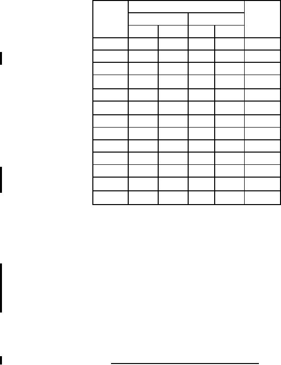
MILPRF19500/370H
Dimensions
Symbol
Notes
Inches
Millimeters
Min
Max
Min
Max
CD
.875
22.23
3
CH
.250
.450
6.35
11.43
HR
.495
.525
12.57
13.34
HR1
.131
.188
3.33
4.78
4
HT
.060
.135
1.52
3.43
L1
.050
1.27
5, 6
LD
.038
.043
0.97
1.09
5, 6
LL
.312
.500
7.92
12.70
5
MHD
.151
.161
3.84
4.09
4
MHS
1.177
1.197
29.90
30.40
PS
.420
.440
10.67
11.18
7
PS1
.205
.225
5.21
5.72
7
S1
.655
.675
16.64
17.15
7
NOTES:
1. Dimensions are in inches. Millimeters are given for general information only.
2. Terminal 1 is the emitter; terminal 2 is the base; and the collector shall be electrically connected to
the case.
3. Body contour is optional within zone defined by dimension CD.
4. Applies to both ends.
5. Applies to both terminals.
6. Dimension LD applies between L1 and LL. Lead diameter shall not exceed twice dimension LD within
dimension L1. Diameter is uncontrolled in dimension L1.
7. These dimensions shall be measured at points .050 inch (1.27 mm) to .055 inch (1.4 mm) below the
seating plane. When gauge is not used, measurement will be made at the seating plane.
8. The seating plane of the header shall be flat within .001 inch (0.03 mm) concave to .004 inch (0.10
mm) convex inside a .930 inch (23.62 mm) diameter circle on the center of the header and flat
within .001 inch (0.03 mm) concave to .006 inch (0.15 mm) convex overall.
9. In accordance with ASME Y14.5M, diameters are equivalent to φx symbology.
FIGURE 1. Physical dimensions ((TO204AA, formerly TO3) Continued.
3
For Parts Inquires call Parts Hangar, Inc (727) 493-0744
© Copyright 2015 Integrated Publishing, Inc.
A Service Disabled Veteran Owned Small Business