MIL-PRF-19500/421G
NOTES:
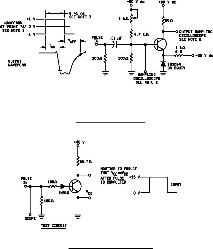
1. The rise time (tr) of the applied pulse shall be ≤ 2.0 ns, duty cycle ≤ 2 percent, and the generator
source impedance shall be 50 Ω.
2. Sampling oscilloscope: ZIN ≥ 100 kΩ, CIN ≤ 12 pF, rise time ≤ 0.2 ns.
3. The signs, polarity symbols, and waveforms shown are for the NPN transistor; the signs and
polarity symbols are reversed for the PNP triode (see 1.2 herein).
FIGURE 6. Nonsaturated switching time test circuit.
NOTE: The input waveform has the following characteristics: PW ≤ 10 µs, duty cycle ≤ 2 percent.
FIGURE 7. Collector emitter nonlatching voltage test circuit.
15
For Parts Inquires call Parts Hangar, Inc (727) 493-0744
© Copyright 2015 Integrated Publishing, Inc.
A Service Disabled Veteran Owned Small Business