MIL-PRF-19500/463K
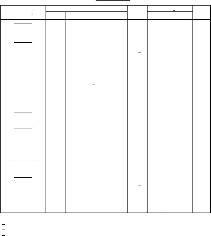
TABLE I. Group A inspection.
Limit 2/
Inspection 1/
Symbol
Unit
Method
Conditions
Min
Max
Subgroup 1
Visual and mechanical
2071
examination
Subgroup 2
Regulator current
VS = 25 V dc, t = 90 s or thermal
Column 3
Column 4
mA dc
IS1 3/
equilibrium, 1N5283-1 through
1N5314-1
t = pulse measurement, 10 ms max
1N7048-1 through 1N7055-1,
Limiting voltage
IL = .8 IS1 (min) 3/, column 3 of
VL
Column 7
V dc
Reverse voltage
IR = 200 mA
VR
2.5
V dc
°C/W
Thermal impedance
3101
See 4.3.3
25
ZθJX
Subgroup 3
Not applicable
Subgroup 4
MΩ
Regulator impedance
VS = 25 V dc; (see figure 7 and
ZS
Column 5
MΩ
Knee impedance
VK = 6.0 V dc, (see figure 8 and
ZK
Column 6
Subgroups 5 and 6
Not applicable
Subgroup 7
Regulator current
VS = column 11 of table II, t = 90 s
Column 10
mA dc
IS2 4/
or thermal equilibrium,
1N5283-1 through 1N5314-1
t = pulse measurement, 10 ms max
1N7048-1 through 1N7055-1,
1/
For sampling plan, see MIL-PRF-19500.
2/
Column references are to table II herein.
3/
Symbol "IP1" may be used in place of "IS1".
4/
Symbol "IP2" may be used in place of "IS2".
13
For Parts Inquires call Parts Hangar, Inc (727) 493-0744
© Copyright 2015 Integrated Publishing, Inc.
A Service Disabled Veteran Owned Small Business