MIL-PRF-19500/495G
*
1.3 Maximum ratings. Unless otherwise specified, TA = +25°C. - Continued
(1) For TA > +25°C, derate linearly 2.86 mW/°C one section, 3.43 mW/°C both sections.
*
(2) For the thermal resistance see figures 4, 5, and 6.
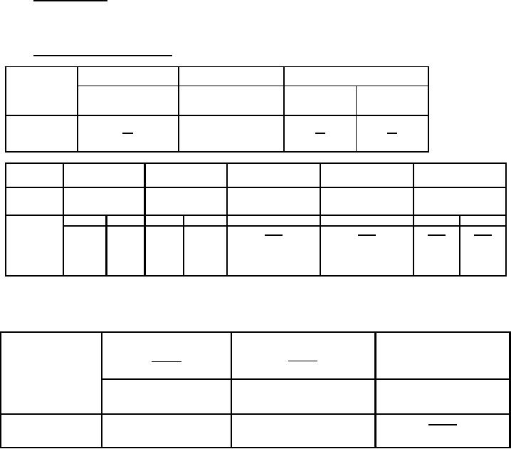
1.4 Primary electrical characteristics. Unless otherwise specified, TA = +25°C.
│hfe│
Switching
COBO
VCB = 10 V dc
VCE = 20 V dc
ton
toff
IE = 0 mA dc
IC = 20 mA dc
f = 100 MHz
100 kHz ≤ f ≤ 1 MHz
pF
ns
ns
Minimum
2.0
Maximum
8.0
10.0
45
310
hFE4 (1)
VCE(sat)1 (1)
VCE(sat)2 (1)
VBE(sat)1 (1)
hFE1
Limits
VCE = 10 V dc
IC = 150 mA dc
VCE = 10 V dc
IC = 300 mA dc
IC = 150 mA dc
IC = 150 mA dc
IB = 15 mA dc
IC = 100 µA dc
IB = 30 mA dc
IB = 15 mA dc
Min
Max
Min
Max
Max
Max
Min
Max
V dc
V dc
V dc
V dc
2N5793
20
40
120
0.3
0.9
0.6
1.2
2N5794
35
100
300
0.3
0.9
0.6
1.2
2N5794U
35
100
300
0.3
0.9
0.6
1.2
2N5794UC
35
100
300
0.3
0.9
0.6
1.2
(1) Pulsed see 4.5.1.
*
1.5 Primary electrical matching characteristics of each individual section.
Limit
| VBE1 - VBE2|
hFE3-1
hFE 2-1
hFE3-2
hFE 2- 2
2N5793A, 2N5794A,
VCE = 10 V dc; IC = 1 mA dc
VCE = 10 V dc; IC = 10 mA dc
VCE = 10 V dc; IC = 1 mA dc
AU, AUC
(1)
(1)
mV dc
Min
0.9
0.9
Max
1.1
1.1
10
(1) The larger number will be replaced in the denominator
2
For Parts Inquires call Parts Hangar, Inc (727) 493-0744
© Copyright 2015 Integrated Publishing, Inc.
A Service Disabled Veteran Owned Small Business