MIL-PRF-19500/117R
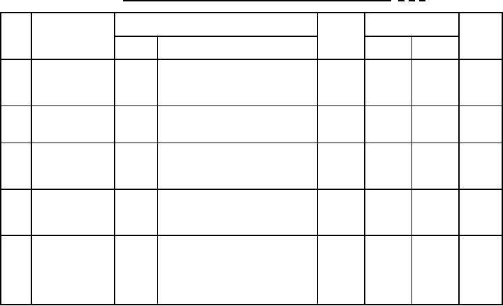
TABLE III. Group B, C, and E electrical and delta end-point measurements. 1/ 2/ 3/
MIL-STD-750
Limits
Step
Inspection
Symbol
Unit
Method
Conditions
Min
Max
μA dc
DC method; VR = column 11 of
IR1
4016
Column
1.
Reverse current
12 of
table IV.
table IV
2.
μA dc
4016
DC method; VR = column 11 of
IR3
2
Reverse current
table IV.
3.
Regulator
V dc
4022
Column
IZ1 = column 5 of table IV.
VZ
voltage (see
Column
4 of
4.5.2)
3 of
table IV
table IV
4.
Ohms
IZ1 = column 5 of table IV.
4051
ZZT
Column
Small-signal
6 of
breakdown
ISIG = 10 percent of IZ rms
table IV
impedance
5.
°C/W
ΔZΘJX
See 4.3.2
3101
10
Thermal
percent
impedance
of initial
value
max.
1/ The electrical measurements for table VIb of MIL-PRF-19500 are as follows:
a. Subgroup 2, see table III herein, steps 1, 3, 4, and 5.
b. Subgroups 3 and 6, see table III herein, steps 2, 3, and 4.
2/ The electrical measurements for table VII of MIL-PRF-19500 are as follows:
a. Subgroup 2, see table III herein, steps 1, 3, 4, and 5.
b. Subgroup 6, see table III herein, steps 2, 3, and 4.
3/ The electrical measurements for table IX of MIL-PRF-19500 are as follows:
a. Subgroup 1, see table III herein, steps 1, 2, 3, 4, and 5.
b. Subgroup 2, see table III herein, steps 2, 3, 4, and 5.
14
For Parts Inquires call Parts Hangar, Inc (727) 493-0744
© Copyright 2015 Integrated Publishing, Inc.
A Service Disabled Veteran Owned Small Business