MIL-PRF-19500/382J
1.3 Maximum ratings, unless otherwise specified TA = +25�C. - Continued.
(4) For non-thermal conductive PCB or unknown PCB surface mount conditions in free air, substitute figure 6 for the
UB package and use RθJA.
(5) TA = +55�C for UB on printed circuit board (PCB), PCB = FR4 .0625 inch (1.59 mm) 1 - layer 1 Oz Cu, horizontal,
still air, pads (UB) = .034 inch (0.86 mm) x .048 inch (1.22 mm), RθJA with a defined thermal resistance condition
included is measured at PT = 400 mW.
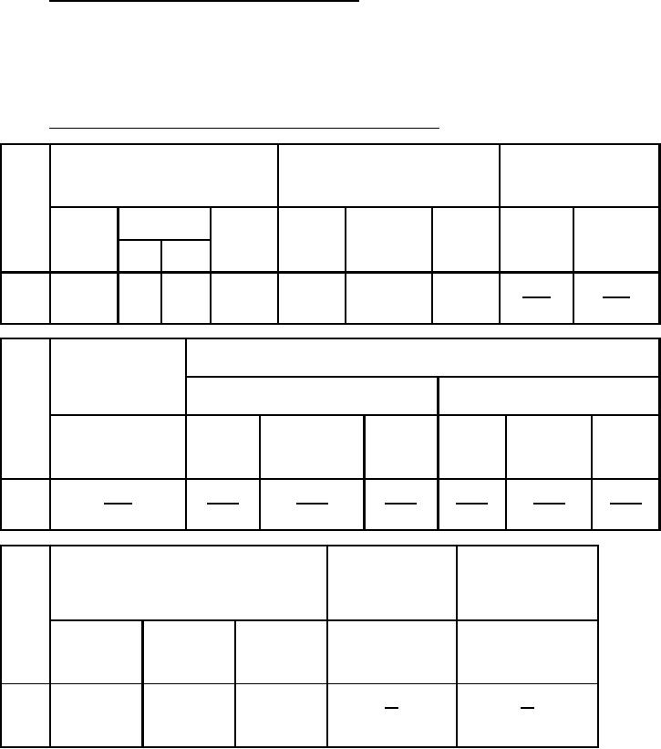
1.4 Primary electrical characteristics unless otherwise specified TA = +25�C.
Limits
hFE1
hFE (inv)1
rec (on)2
VCE = -0.5 V dc
VEC = -0.5 V dc
IB = -1 mA dc
IE = -200 �A dc
Ie = 100 �A ac(rms)
IC = -1 mA dc
IE = 0; f = 1 kHz
2N2944A,
2N2945
2N2946A,
2N2944A,
2N2945A,
2N2946A,
2N2944A,
2N2945A,
UB
UB
UB
2N2945AUB,
UB
UB
2N2945AUB,
A,
AM,
2N2945AM,
2N2945AM,
UB
AUBM
2N2945AUBM
2N2945AUBM
ohms
ohms
Min
100
70
70
50
50
30
20
Max
200
4
6
Limits
rec (on)2
IB = -1 mA dc
VEC (ofs)
Ie = 100 �A ac(rms)
IB = -200 �A dc
IE = 0; f = 1 kHz
Ib = -1.0 mA dc
IE = 0
IE = 0
2N2946A,
2N2944A,
2N2945A,
2N2946A,
2N2944A,
2N2945A,
2N2946A,
UB
UB
2N2945AUB,
UB
UB
2N2945AUB,
UB
2N2945AM,
2N2945AM,
2N2945AUBM
2N2945AUBM
ohms
mV dc
mV dc
mV dc
mV dc
mV dc
mV dc
Min
Max
8
-0.3
-0.5
-0.8
-0.6
-1.0
-2.0
hfe
Limits
Cobo
Cibo
VCB = -6 V dc
VEB = -6 V dc
IE = 0
f = 1 MHz
IC = 0
100 kHz ≤ f ≤1 MHz
100 kHz ≤ f ≤ 1 MHz
VCE = -6 V dc
IC = -1 mA dc
2N2945A,
2N2944A,
2N2945A,
2N2946A,
2N2945AUB,
UB
2N2945AUB,
UB
2N2945AM,
2N2945AM,
2N2945AUBM
2N2945AUBM
pF
pF
Min
15
10
5
Max
55
55
55
10
6
2
For Parts Inquires call Parts Hangar, Inc (727) 493-0744
© Copyright 2015 Integrated Publishing, Inc.
A Service Disabled Veteran Owned Small Business