MIL-PRF-19500/426H
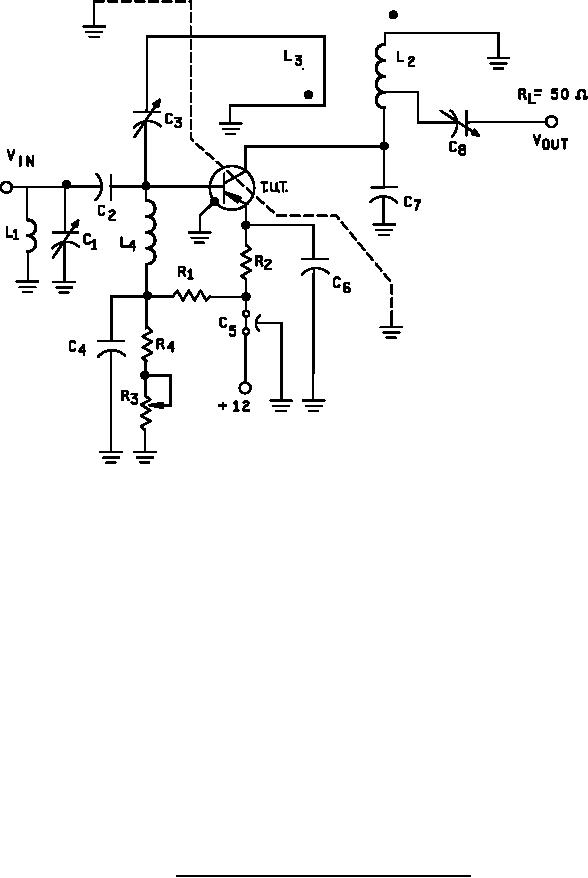
Values:
C1, C7
= 1-10 pF (variable air-piston type capacitors)
C2, C4, C6
= 500 pF (button type capacitors)
C3, C8
= .4 - 6.0 pF (variable air-piston type capacitors)
C5
= 1,000 pF
= 2.7 kΩ
R1
R2, R4 = 1 kΩ
= 20 kΩ
R3
L1 = silver-plated brass bar, 1.0 inch (25.4 mm) long by .25 inch (6.35 mm) o.d. (straight bar).
L2 = silver-plated brass bar, 1.5 inches (38.1 mm) long by .25 inch (6.35 mm) o.d. Tap is .25 inch (6.35 mm)
from collector (straight bar).
L3 = One-half turn of AWG number 16 wire, loop o.d. approximately .5 inch (12.7 mm), located .25 inch (6.35 mm)
from, and parallel to L2.
L4 = 0.22 µH.
The noise source is a hot-cold body, (all type 70 or equivalent) with a test receiver (all type 70 or equivalent).
FIGURE 5. RF amplifier for power gain and noise figure tests.
17
For Parts Inquires call Parts Hangar, Inc (727) 493-0744
© Copyright 2015 Integrated Publishing, Inc.
A Service Disabled Veteran Owned Small Business