MIL-PRF-19500/445D
4.4.3 Group C inspection. Group C inspection shall be conducted in accordance with the conditions specified for subgroup testing in
table VII of MIL-PRF-19500, and as follows. Electrical measurements (end-points) shall be in accordance with table I, group A, subgroup
2 herein.
Subgroup
Method
Condition
C2
2036
(Not applicable to surface mount devices); Lead fatigue conditions: Test condition E; .062 inch
(1.57 mm) lead restriction from case. Tension conditions: Test condition A; 4 pounds, 15 seconds.
C3
2056
Nonoperating (not required for double plug metallurgical bonded device).
C3
2006
20,000 g's; Y1, Y2, X1 (Not required for double plug metallurgical bonded device).
C6
1038
High temperature reverse bias (HTRB), test condition A, VR = 12.8 V;
TA = +150°C.
4.5 Methods of inspection. Methods of inspection shall be as specified in the appropriate tables and as follows.
4.5 Methods of inspection. Methods of inspection shall be as specified in the appropriate tables and as follows.
4.5.1 Steady-state operation life. This test shall be conducted with a half-sine wave of the specified peak voltage impressed across
the diode in the reverse direction followed by a half-sine waveform of the specified average rectified current. The forward conduction
angle of the rectified current shall not be greater than 180° nor less than 150°.
4.5.2 Thermal resistance. Thermal resistance measurement shall be in accordance with MIL-STD-750, method 3101 or 4081.
Forced moving air or draft shall not be permitted across the device during test. The maximum limit for RΘJL under these test conditions
shall be as shown in group E. The following conditions shall apply when using method 3101:
a.
IM ...............................................................1 mA to 10 mA
b.
IH ...............................................................25 mA to 100 mA
c.
tH ................................................................25 seconds minimum
tMD .............................................................70 µs maximum
d.
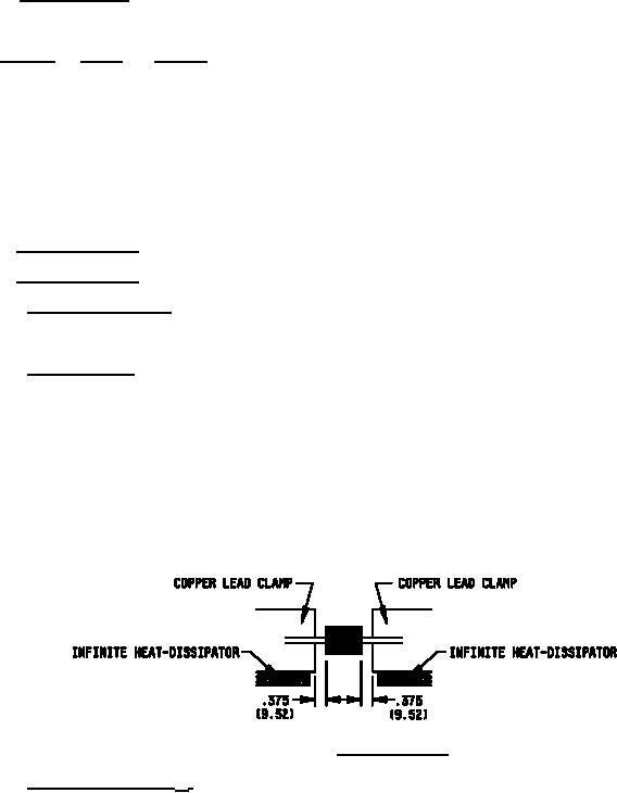
LS = Lead spacing = 9.53 mm (.375 inch) minimum for leaded devices and LS = 0 minimum for unleaded devices as defined on figure
4 below:
LS = Lead spacing = .375 inch (9.52 mm) as defined on figure 4 below:
FIGURE 4. Mounting conditions.
4.5.3 Effective carrier lifetime (τ CL). This test shall be measured with the device installed in the test fixture, drawing C68001
using the test setup shown on figure 5 herein. Adjust the signal generator to 54 MHz and maximum output in order to obtain a sufficient
trigger signal for the oscilloscope. Adjust the sensitivity of the oscilloscope to 20 mV/cm. With the device in the test fixture, adjust the
output of the amplifier until the peak amplitude of the forward current is 20 mA or 5 cm as seen on the oscilloscope. Change sensitivity of
scope to 2 mV/cm. Under these conditions, the effective carrier lifetime is related to the amplitude designated as "τCL" shown on figure 6.
This amplitude has the calibration of 50 ps/cm.
10
For Parts Inquires call Parts Hangar, Inc (727) 493-0744
© Copyright 2015 Integrated Publishing, Inc.
A Service Disabled Veteran Owned Small Business