MIL-PRF-19500/604B
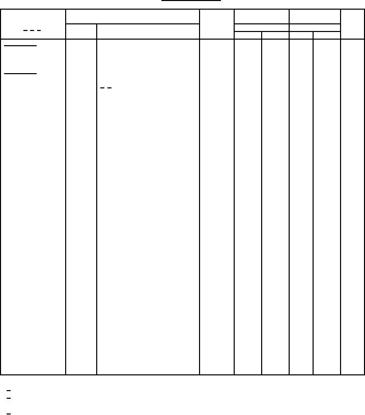
TABLE II. Group D inspection.
Inspection
MIL-STD-750
Symbol
Pre-irradiation
Post-irradiation
Unit
limits
limits
1/ 2/ 3/
M, D, and R
M, D, and R
Method
Conditions
Min
Max
Min
Max
Subgroup 1
Not applicable
TC = + 25°C
Subgroup 2
1019
2/ 3/
Steady-state total
dose irradiation
End-point electricals
Breakdown voltage,
3407
VGS = 0; ID = 1 mA;
V(BR)DSS
drain to source
bias condition C
2N7272
100
100
V dc
2N7275
200
200
V dc
2N7278
250
250
V dc
2N7281
500
500
V dc
3403
VDS = VGS; ID = 1 mA
VGS(th)1
2
4
2
4
V dc
Gate to source
voltage (threshold)
3411
VGS = 20 V; VDS = 0;
IGSSF1
100
100
nA dc
Gate current
bias condition C
3411
VGS = -20 V; VDS = 0,
IGSSR1
-100
-100
nA dc
Gate Current
bias condition C
µA dc
IDSS1
25
25
3413
VGS = 0; VDS = 80 percent of rated
Drain current
VDS (preirradiation); bias condition
C
RDS(on)1
3421
VGS = 10 V, condition A, pulsed,
Static drain to
see 4.5.1; ID = ID2
source on-state
resistance
Ω
2N7272
0.180
0.180
Ω
2N7275
0.500
0.500
Ω
2N7278
0.700
0.700
Ω
2N7281
2.50
2.50
VDS(on)
Drain to source on-
3405
VGS = 10 V, condition A, pulsed,
see 4.5.1; ID = ID1
state voltage
2N7272
1.51
1.51
V dc
2N7275
2.63
2.63
V dc
2N7278
2.94
2.94
V dc
2N7281
5.25
5.25
V dc
1/
For sampling plan see MIL-PRF-19500.
2/
Inspection requires all subgroup 2 (group D) measurements after exposure to both of the following
insitu bias conditions: VGS = 10 V; VDS = 0; VGS = 0 V; VDS = 80 percent of rated VDS.
3/
Each bias condition requires a separate total dose sample.
13
For Parts Inquires call Parts Hangar, Inc (727) 493-0744
© Copyright 2015 Integrated Publishing, Inc.
A Service Disabled Veteran Owned Small Business