MIL-PRF-19500/323N
Procedure:
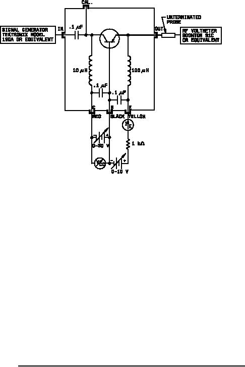
1. Set signal generator to 31.8 MHz and connect to "IN" connector on test jig.
2. Connect low voltage dc power supplies as shown. A 1 K ohm resistor should be placed in series with the
emitter power supply to prevent damage to transistors being tested.
3. Set collector supply for VCE = -20 V dc, and emitter supply for IC = -10 mA.
4. Connect RF voltmeter with unterminated probe adapter to "CAL" connector on test jig. Adjust signal
generator until RF voltage is 1 volt. (NOTE: Decade switching of voltmeter should be accurate from 1 mV to
3 volts. If not, input voltage may be set using voltage dividers, utilizing lower scales of the RF voltmeter. If
this is done, the voltage dividers should be left in place when the voltmeter is removed, as they constitute a
load on the input of the circuit.)
5. Remove RF voltmeter from "CAL" connector and connect to "OUT" connector. Meter will now read rb'Cc as
follows:
Meter range full scale
3 mV
10 mV
30 mV
.1 volt
FIGURE 10. Collector-base time constant test circuit (an equivalent circuit may be used).
26
For Parts Inquires call Parts Hangar, Inc (727) 493-0744
© Copyright 2015 Integrated Publishing, Inc.
A Service Disabled Veteran Owned Small Business