MIL-PRF-19500/356L
6.4.2 PCB mounting with FR4 material for only 1.5 Watts. For a PCB mounting example with FR4 material where
only 1.5 Watts of power is used at a TJ of 175ºC and ambient temperature of 55ºC, the following steps guide the user
in what the PCB pad size will need to be in area for each pad with 1 ounce, 2 ounce, and 3 ounce copper. For axial-
leaded, the lead length for mounting will be .187 inch (4.76 mm) or less from body to entry point on PCB surface.
a. Calculate maximum thermal resistance allowed from junction to ambient (175ºC to 55ºC) for the required
1.5 Watts: RθJA = (175ºC - 55ºC)/1.5 W = 80ºC/W.
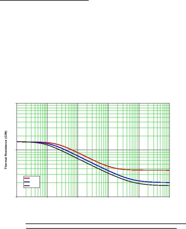
b. Find thermal resistance of 80ºC/W on Y-axis in figure 9 using a thermal resistance versus pad area plot on
one of the three curves for different weights of copper cladding and then intersect curve horizontally to get
answer. These curves assume still air, horizontal position.
c. The answer is: 1 ounce PCB = .13 in2(3.3 mm2), 2 ounce PCB = .082 in2(2.08 mm2), 3 ounce PCB = .055
in2(1.4 mm2) for each pad.
d. Add a conservative guard-band to the pad size (larger) to keep TJ below 175ºC.
B-Pkg/E-Pkg MELF/Axial Thermal Resistance vs FR4 Pad Area
Still Air, PCB Horizontal
1000
100
1oz Foil
2oz Foil
3oz Foil
10
0.001
0.01
0.1
1
10
100
Pad Area per Pad (in2)
* FIGURE 9. Thermal resistance versus FR4 pad area still air, PCB horizontal (for each pad) with 1 ounce
copper (top curve), 2 ounce copper (middle curve), and 3 ounce copper (bottom curve).
24
For Parts Inquires call Parts Hangar, Inc (727) 493-0744
© Copyright 2015 Integrated Publishing, Inc.
A Service Disabled Veteran Owned Small Business