MIL-PRF-19500/398K
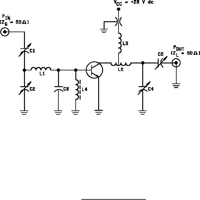
C1, C2, C5 = 3 - 35 pF.
C3 = 24 pF (see note).
C4 = 0.4 - 7 pF.
L1 = Straight piece number 16 bare tin wire, .625 inch (15.87 mm) long.
L2 = 3 turns number 16 wire, .250 inch (6.35 mm) ID, .312 inch (7.92 mm) long.
L3 = 1 turns number 18 wire, .250 inch (6.35 mm) ID, .022 inch (0.56 mm) long.
L4 = Ferrite RF choke, Z = 450 Ω.
NOTE: For optimum performance, C3 should be mounted as close as possible to base lead.
FIGURE 4. Power output test circuit (400 MHz).
18
For Parts Inquires call Parts Hangar, Inc (727) 493-0744
© Copyright 2015 Integrated Publishing, Inc.
A Service Disabled Veteran Owned Small Business