MILPRF19500/586L
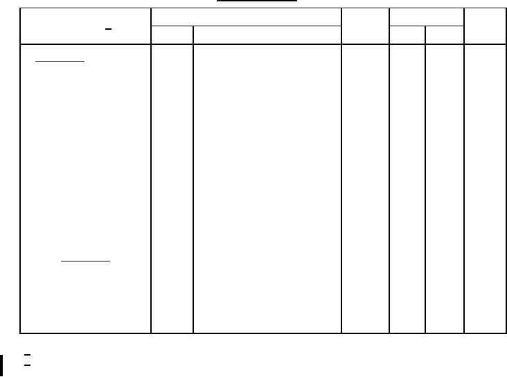
TABLE I. Group A inspection Continued.
Limits
Inspection 1/
Symbol
Unit
Method
Condition
Min
Max
Subgroup 3 - Continued
4011
Forward voltage
IF = 1.0 A (pk)
VF4
1N5817-1, 1N5817UR-1
.40
V dc
1N5819-1, 1N5819UR-1
Pulse method (see 4.5.1)
.45
V dc
1N6761-1, 1N6761UR-1
.64
V dc
TA = 55°C
Low temperature operation:
Forward voltage
4011
IF = 1.0 A (pk)
VF5
1N5817-1, 1N5817UR-1
.60
V dc
1N5819-1, 1N5819UR-1
Pulse method (see 4.5.1)
.65
V dc
1N6761-1, 1N6761UR-1
.80
V dc
Reverse current leakage
4016
µA
VRM = 20 V (pk)
IR
1N5817-1, 1N5817UR-1
100
µA
VRM = 45 V (pk)
1N5819-1, 1N5819UR-1
200
µA
VRM = 90 V (pk)
1N6761-1, 1N6761UR-1
400
Subgroup 4
VR = 5 V dc, .01 ≤ f ≤ 1 MHz,
CT
Capacitance
4001
VSIG = 15 mV p-p
1N5817-1, 1N5817UR-1
110
pF
1N5819-1, 1N5819UR-1
70
pF
1N6761-1, 1N6761UR-1
70
pF
For sampling plan, see MILPRF19500.
1/
2/
Electrical characteristics for all UR devices are identical to the corresponding axial leaded devices unless
otherwise specified.
12
For Parts Inquires call Parts Hangar, Inc (727) 493-0744
© Copyright 2015 Integrated Publishing, Inc.
A Service Disabled Veteran Owned Small Business