MILPRF19500/586L
4.3 Screening.
4.3.1 Screening of packaged devices (JANTX, JANTXV and JANS levels only). Screening of packaged devices
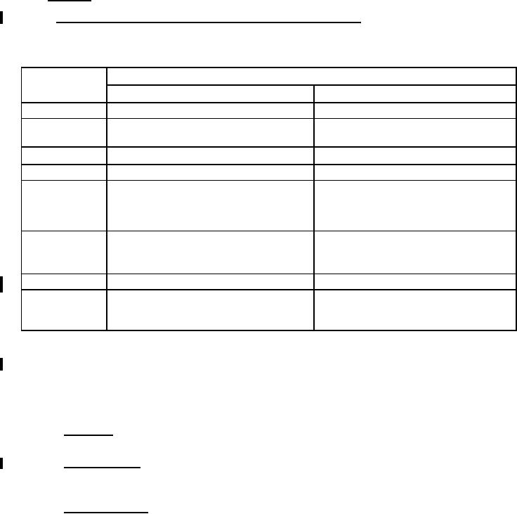
shall be in accordance with table EIV of MILPRF19500, and as specified herein. The following measurements
shall be made in accordance with table I herein. Devices that exceed the limits of table I herein shall not be
acceptable.
Screen
Measurement
(see table EIV of
JANS level
JANTXV and JANTX level
2
Not required
Not required
Not applicable
Not applicable
3b
3c (1)
Required (see 4.3.1.3)
Required (see 4.3.1.3)
4, 5, and 6
Not applicable
Not applicable
IR1 and VF2
9
Not applicable
TA = +110°C; VRWM = 20 V(pk), 1N5817,
TA = +110°C; VRWM = 20 V(pk), 1N5817,
TA = +110°C; VRWM = 45 V(pk), 1N5819,
TA = +110°C; VRWM = 45 V(pk), 1N5819,
10 (2)
TA = +100°C; VRWM = 100 V(pk), 1N6761,
TA = +100°C; VRWM = 100 V(pk), 1N6761,
IO = 0, VR = VRWM
IO = 0, VR = VRWM
ĆIR1 ≤ 100 percent of initial reading or .02 mA,
IR1 and VF2
11
whichever is greater.
ĆVF2 ≤ ±50 mV dc
12
See 4.3.1.2
See 4.3.1.2
Subgroup 2 of table I herein;
Subgroup 2 of table I herein;
ĆIR1 ≤ 100 percent of initial reading or .02 mA,
ĆIR1 ≤ 100 percent of initial reading or .02 mA,
13
whichever is greater; ĆVF2 ≤ ±50 mV dc
whichever is greater; ĆVF2 ≤ ±50 mV dc
(1) Thermal impedance shall be performed any time after sealing provided temperature cycling is performed in
accordance with table E-IV of MILPRF19500, screen 3 prior to this thermal test.
(2) Test time shall be 48 hours minimum. TJ is not to exceed +115°C at VRWM. TJ is affected by the device
mounting thermal resistance when parasitic power is generated by the temperature dependent leakage current.
Until this leakage becomes significant near thermal runaway, TJ remains approximately equal to TA or TJ for IO
= 0.
4.3.1.1 JAN testing. JAN level product will have temperature cycling and thermal impedance testing performed in
accordance with MILPRF19500, JANTX level screening level requirements.
4.3.1.2 Burn-in conditions. Burn-in conditions shall be as follows: IF = 1.0 A dc (minimum), adjust IF or TA to
achieve TJ = +100°C min. Mounting and test conditions shall be in accordance with method 1038 of
MILSTD750, test condition B.
4.3.1.3 Thermal impedance. The thermal impedance measurements shall be performed in accordance with
method 3101 or 4081 of MILSTD750 using the guidelines in that method for determining IM, IH, tH, tSW.
8
For Parts Inquires call Parts Hangar, Inc (727) 493-0744
© Copyright 2015 Integrated Publishing, Inc.
A Service Disabled Veteran Owned Small Business