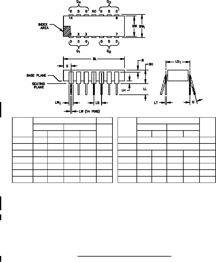
MILŁPRFŁ19500/598C
Dimensions
Dimensions
Symbol
Inches
Millimeters
Notes
Symbol
Inches
Millimeters
Notes
Min
Max
Min
Max
Min
Max
Min
Max
BH
.105
.175
2.67
4.45
4
LS
.300 TP
7.62 TP
7
BL
.690
.770
17.53
19.56
LS1
.100 TP
2.54 TP
7
.280
.310
7.11
7.87
BW
LW1
.038
.060
0.97
1.52
BW1
.290
.325
7.37
8.26
5
LW
.015
.021
0.381
0.533
6
LH
.025
.055
0.64
1.40
4, 6
R
.010
0.25
LL
.125
.175
3.18
4.45
4
S
.030
.095
0.76
2.41
α
0░
15░
0░
15░
LT
.008
.012
0.203
0.305
8
NOTES:
1. Dimensions are in inches. Millimeters are for general information only.
2. Pin-out: G = gate, S = source, D = drain, and NC = not connected.
3. Index area: A notch or a pin 1 identification mark shall be located adjacent to pin 1. The manufacturer's
identification shall not be used as a pin 1 identification mark.
4. This dimension shall be measured with the device seated in seating plane gauge JEDEC Outline No. GSŁ3.
5. Lead center when α is 0░. BW1 shall be measured at the centerline of the leads.
6. Outlines on which the seating plane is coincident with the base plane (LH = 0), terminals lead standoffs are
not required, and LW1 may equal LW along any part of the lead above the seating/base plane.
7. Leads within .005 inch (0.13 mm) radius of True Position (TP) at gauge plane with maximum material
condition and unit installed. Twelve spaces.
8. α applies to spread leads prior to installation.
9. Dimensioning and tolerancing in accordance with ASME Y14.5.
FIGURE 1. Physical dimensions and configuration (MOŁ036AB).
3
For Parts Inquires call Parts Hangar, Inc (727) 493-0744
© Copyright 2015 Integrated Publishing, Inc.
A Service Disabled Veteran Owned Small Business