MILPRF19500/472F
Dimensions
Symbol
Inches
Millimeters
Notes
Min
Max
Min
Max
CD
.620
15.75
CH
.250
.340
6.35
8.64
HT
.050
.075
1.27
1.91
3
HR
.350
8.89
.115
.145
2.92
3.68
HR1
LD
.028
.034
0.711
0.863
4
LL
.360
.500
9.14
12.70
4
.050
1.27
4
L1
MHD
.142
.152
3.61
3.86
MHS
.958
.962
24.33
24.43
PS
.190
.210
4.83
5.33
.093
.105
2.36
2.67
PS1
S
.570
.590
14.48
14.99
T
.190
.210
4.83
5.33
NOTES:
1.
Dimensions are in inches. Millimeters are given for general information only.
2.
Internal resistance (typically 750 ohms). This resistor is optional.
3.
The outline contour is optional.
4.
Dimension does not include sealing flanges.
5.
All leads.
6.
Terminal designation is as follows: 1 emitter, 2 base (B1), 3 base (B2). The collector shall be
connected to the case.
7.
Shape of capweld flange is optional and cannot extend beyond dimension HR.
In accordance with ASME Y14.5M, diameters are equivalent to φx symbology.
8.
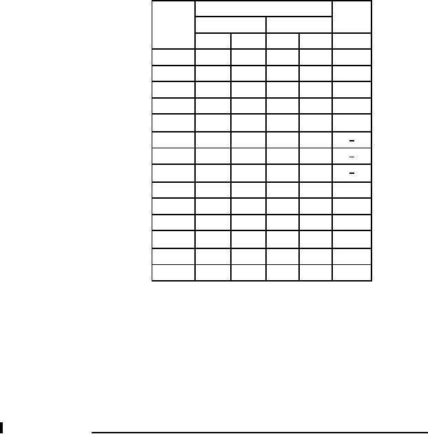
FIGURE 2. Physical dimensions (3-pin TO66) and schematic circuit for 2N6352 and 2N6353 Continued.
6
For Parts Inquires call Parts Hangar, Inc (727) 493-0744
© Copyright 2015 Integrated Publishing, Inc.
A Service Disabled Veteran Owned Small Business